Configuring an ospf nssa area, Network requirements, Configuration procedure – H3C Technologies H3C S10500 Series Switches User Manual
Page 127
112
[SwitchA] ospf
[SwitchA-ospf-1] area 1
[SwitchA-ospf-1-area-0.0.0.1] stub no-summary
[SwitchA-ospf-1-area-0.0.0.1] quit
# Display OSPF routing information on Switch C.
[SwitchC] display ospf routing
OSPF Process 1 with Router ID 10.4.1.1
Routing Tables
Routing for Network
Destination Cost Type NextHop AdvRouter Area
0.0.0.0/0 4 Inter 10.2.1.1 10.2.1.1 0.0.0.1
10.2.1.0/24 3 Transit 10.2.1.2 10.4.1.1 0.0.0.1
10.4.1.0/24 3 Stub 10.4.1.1 10.4.1.1 0.0.0.1
Total Nets: 3
Intra Area: 2 Inter Area: 1 ASE: 0 NSSA: 0
NOTE:
After this configuration, routing entries on the stub router are further reduced, containing only one default
external route.
Configuring an OSPF NSSA area
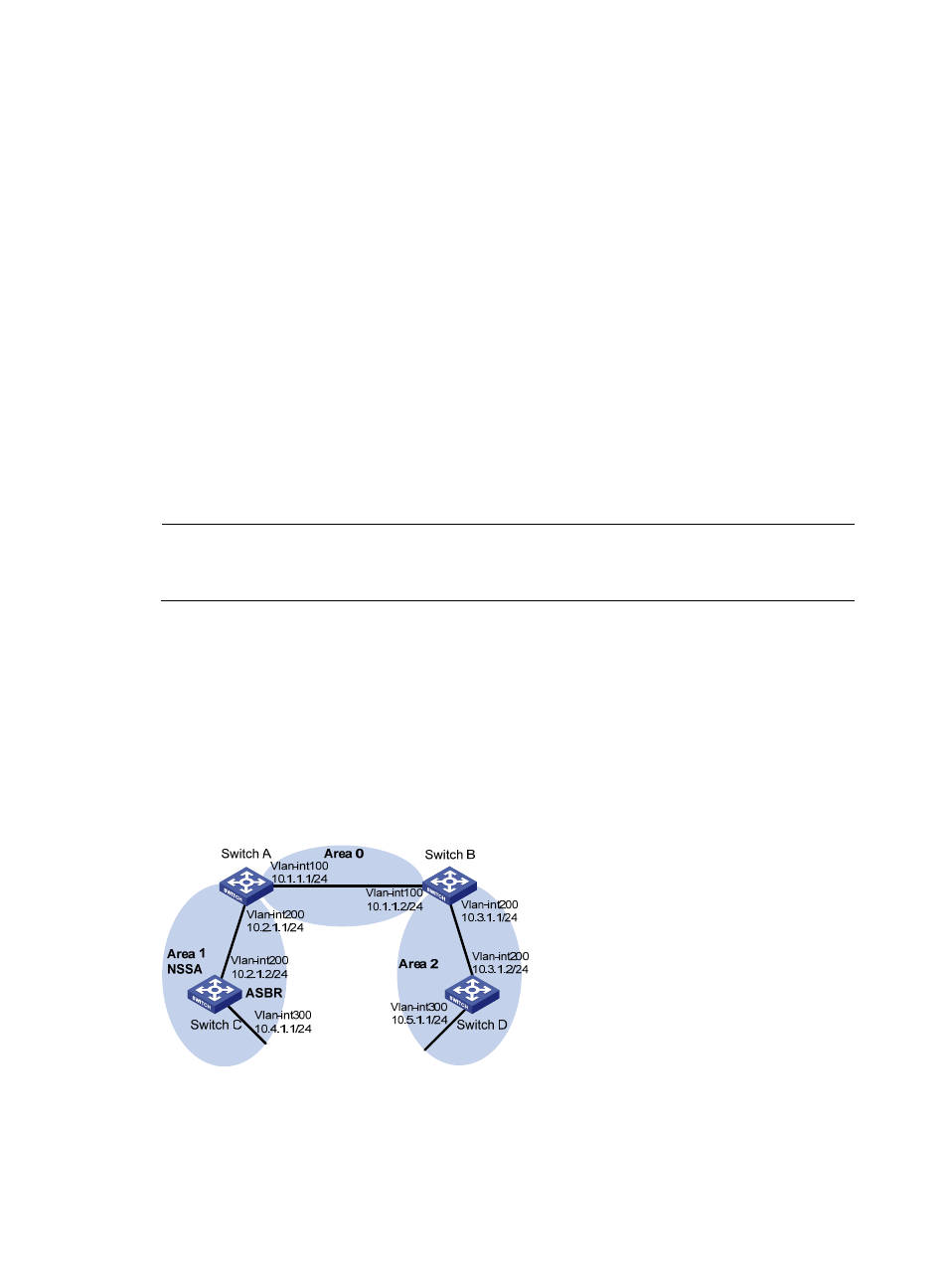
Network requirements
shows an AS is split into three areas, where all switches run OSPF. Switch A and Switch B act
as ABRs to forward routing information between areas.
Configure Area 1 as an NSSA area and configure Switch C as the ASBR to redistribute static routes into
the AS.
Figure 42 Network diagram for OSPF NSSA area configuration
Configuration procedure
1.
Configure IP addresses for interfaces.
2.
Configure OSPF basic functions. (See “
Configuring OSPF basic functions
”)