Configuration procedure – H3C Technologies H3C S10500 Series Switches User Manual
Page 319
304
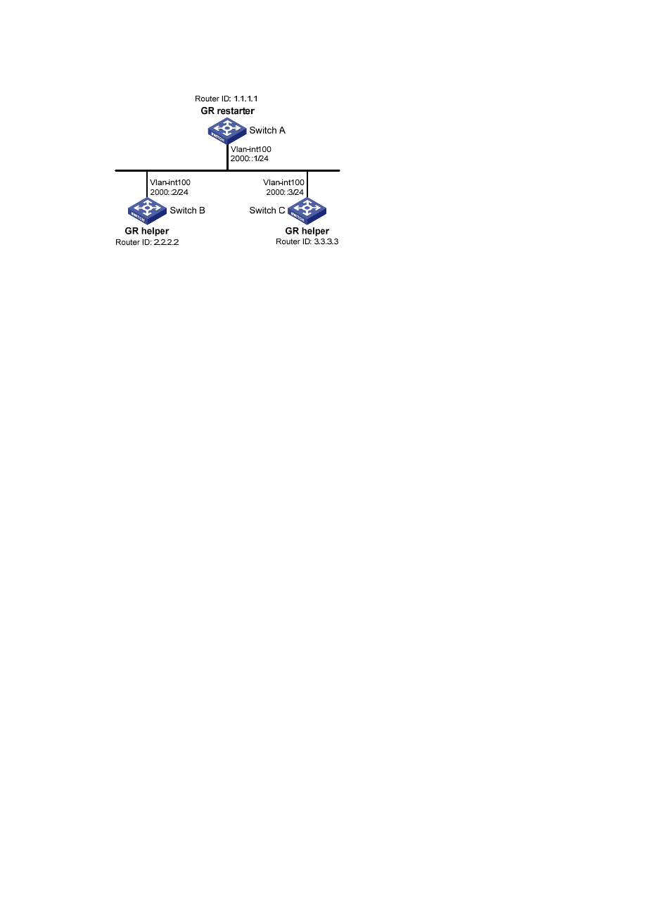
Figure 109 Network diagram for OSPFv3 GR configuration
Configuration procedure
1.
Configure IPv6 addresses for interfaces. (Details not shown)
2.
Configure OSPFv3 basic functions.
# On Switch A, enable OSPFv3 process 1, enable GR, and set the router ID to 1.1.1.1.
<SwitchA> system-view
[SwitchA] ipv6
[SwitchA] ospfv3 1
[SwitchA-ospfv3-1] router-id 1.1.1.1
[SwitchA-ospfv3-1] graceful-restart enable
[SwitchA-ospfv3-1] quit
[SwitchA] interface vlan-interface 100
[SwitchA-Vlan-interface100] ospfv3 1 area 1
[SwitchA-Vlan-interface100] quit
# Enable OSPFv3 on Switch B and set the router ID to 2.2.2.2. (By default, GR helper is enabled on
Switch B).
<SwitchB> system-view
[SwitchB] ipv6
[SwitchB] ospfv3 1
[SwitchB-ospfv3-1] router-id 2.2.2.2
[SwitchB-ospfv3-1] quit
[SwitchB] interface vlan-interface 100
[SwitchB-Vlan-interface100] ospfv3 1 area 1
[SwitchB-Vlan-interface100] quit
# Enable OSPFv3 on Switch C and set the router ID to 3.3.3.3. (By default, GR helper is enabled on
Switch C).
<SwitchC> system-view
[SwitchC] ipv6
[SwitchC] ospfv3 1
[SwitchC-ospfv3-1] router-id 3.3.3.3
[SwitchC-ospfv3-1] quit
[SwitchC] interface vlan-interface 100
[SwitchC-Vlan-interface100] ospfv3 1 area 1
[SwitchC-Vlan-interface100] quit
3.
Verify the configuration.