Configuring ospf graceful restart, Network requirements, Configuration procedure – H3C Technologies H3C S10500 Series Switches User Manual
Page 135
120
[SwitchB-ospf-1-area-0.0.0.1] quit
[SwitchB-ospf-1] quit
# Configure Switch C.
[SwitchC] ospf 1
[SwitchC-ospf-1] area 1
[SwitchC-ospf-1-area-0.0.0.1] vlink-peer 2.2.2.2
[SwitchC-ospf-1-area-0.0.0.1] quit
# Display the OSPF routing table of Switch B.
[SwitchB] display ospf routing
OSPF Process 1 with Router ID 2.2.2.2
Routing Tables
Routing for Network
Destination Cost Type NextHop AdvRouter Area
10.2.1.0/24 2 Transit 10.2.1.1 3.3.3.3 0.0.0.1
10.3.1.0/24 5 Inter 10.2.1.2 3.3.3.3 0.0.0.0
10.1.1.0/24 2 Transit 10.1.1.2 2.2.2.2 0.0.0.0
Total Nets: 3
Intra Area: 2 Inter Area: 1 ASE: 0 NSSA: 0
Switch B has learned the route 10.3.1.0/24 to Area 2.
Configuring OSPF Graceful Restart
Network requirements
As shown in
:
•
Switch A, Switch B, and Switch C that belong to the same autonomous system and the same OSPF
routing domain are GR capable.
•
Switch A acts as the non-IETF standard GR Restarter, whereas Switch B and Switch C are the GR
Helpers and re-synchronize their LSDB with Switch A through OOB communication of GR.
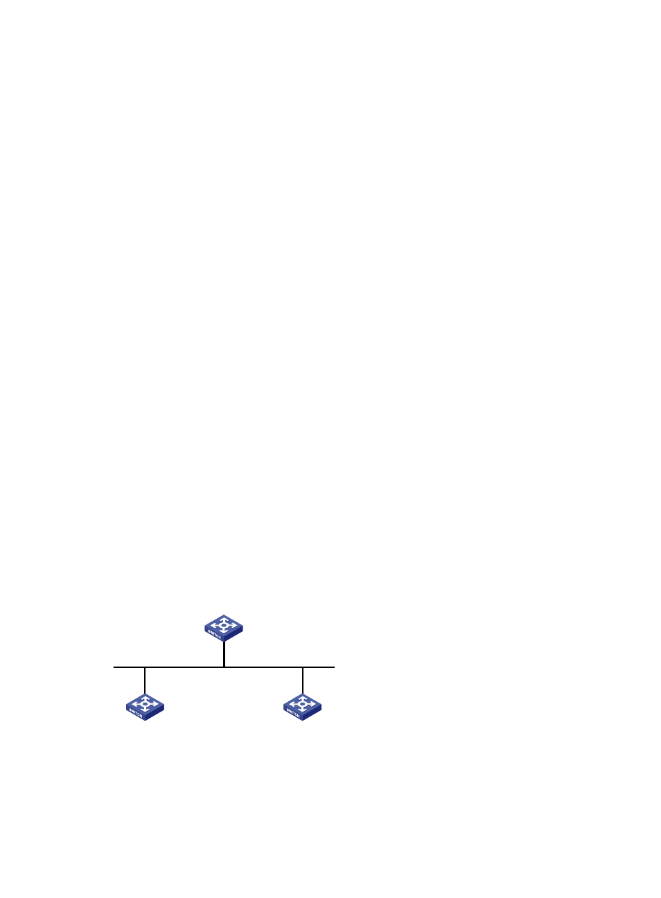
Figure 45 Network diagram for OSPF GR configuration
Vlan-int100
192.1.1.1/24
Vlan-int100
192.1.1.3/24
Vlan-int100
192.1.1.2/24
GR helper
GR helper
GR restarter
Switch A
Switch C
Switch B
Router ID: 1.1.1.1
Router ID: 2.2.2.2
Router ID: 3.3.3.3
Configuration procedure
1.
Configure IP addresses for interfaces. (Details not shown)
2.
Configure OSPF basic functions.