Dis election configuration, Network requirements, Configuration procedure – H3C Technologies H3C S10500 Series Switches User Manual
Page 187
172
10.1.2.0/24 10 NULL Vlan200 Direct D/L/-
172.16.0.0/16 20 NULL Vlan300 192.168.0.2 R/-/-
Flags: D-Direct, R-Added to RM, L-Advertised in LSPs, U-Up/Down Bit Set
[SwitchD] display isis route
Route information for ISIS(1)
-----------------------------
ISIS(1) IPv4 Level-2 Forwarding Table
-------------------------------------
IPV4 Destination IntCost ExtCost ExitInterface NextHop Flags
--------------------------------------------------------------------------
192.168.0.0/24 10 NULL Vlan300 Direct D/L/-
10.1.1.0/24 20 NULL Vlan300 192.168.0.1 R/-/-
10.1.2.0/24 20 NULL Vlan300 192.168.0.1 R/-/-
172.16.0.0/16 10 NULL Vlan100 Direct D/L/-
Flags: D-Direct, R-Added to RM, L-Advertised in LSPs, U-Up/Down Bit Set
DIS election configuration
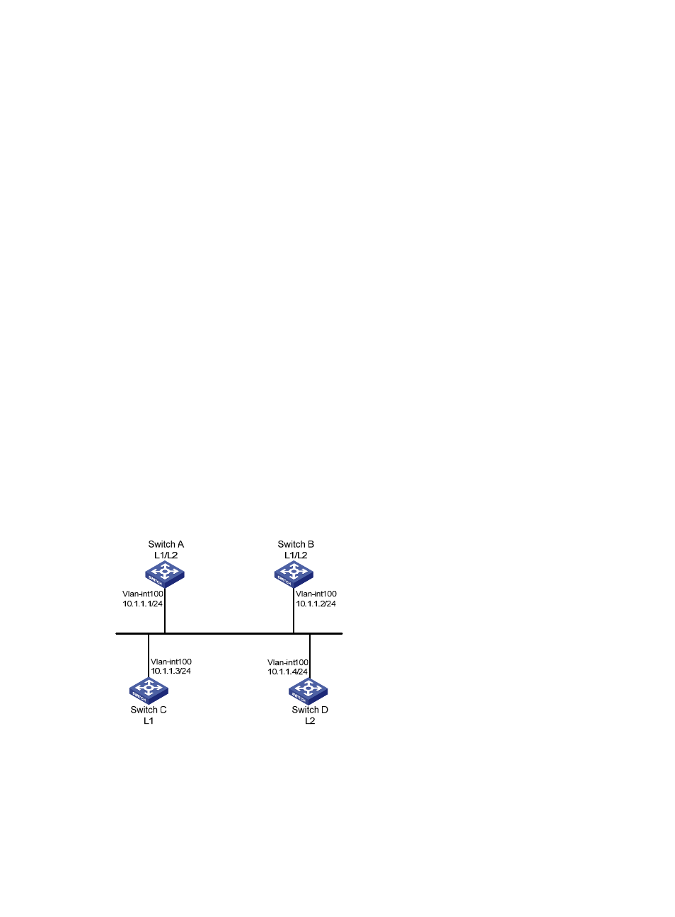
Network requirements
As shown in
, Switch A, B, C, and D reside in IS-IS area 10 on a broadcast network (Ethernet).
Switch A and Switch B are Level-1-2 switches, Switch C is a Level-1 switch, and Switch D is a Level-2 switch.
Change the DIS priority of Switch A to make it elected as the Level-1-2 DIS router.
Figure 65 Network diagram for DIS selection
Configuration procedure
1.
Configure an IP address for each interface. (Details not shown)
2.
Enable IS-IS.
# Configure Switch A.
<SwitchA> system-view