Configuration procedure – H3C Technologies H3C S10500 Series Switches User Manual
Page 360
345
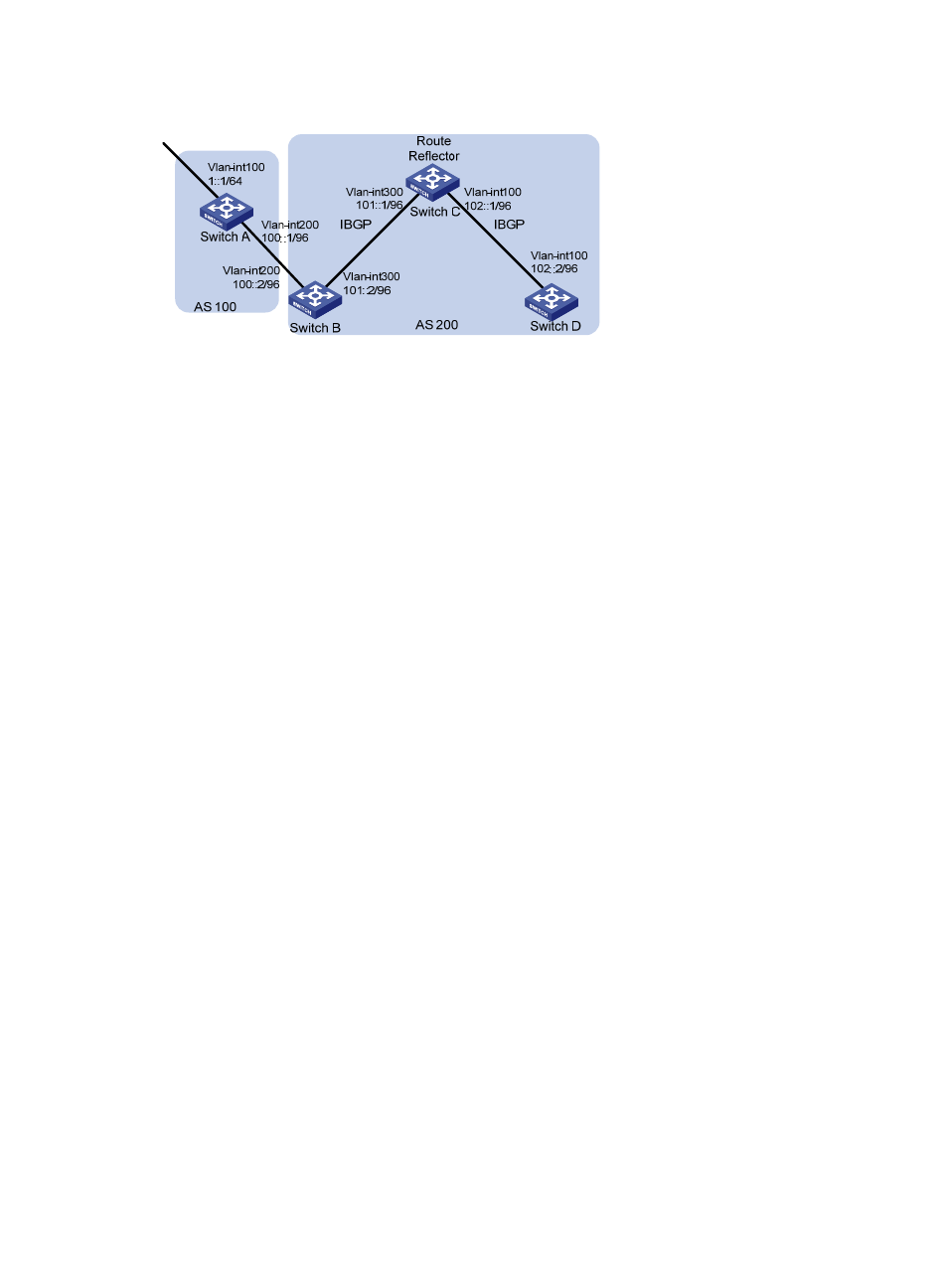
Figure 114 Network diagram for IPv6 BGP route reflector configuration
Configuration procedure
1.
Configure IPv6 addresses for VLAN interfaces. (Details not shown)
2.
Configure IPv6 BGP basic functions.
# Configure Switch A.
<SwitchA> system-view
[SwitchA] ipv6
[SwitchA] bgp 100
[SwitchA-bgp] router-id 1.1.1.1
[SwitchA-bgp] ipv6-family
[SwitchA-bgp-af-ipv6] peer 100::2 as-number 200
[SwitchA-bgp-af-ipv6] network 1:: 64
#Configure Switch B.
<SwitchB> system-view
[SwitchB] ipv6
[SwitchB] bgp 200
[SwitchB-bgp] router-id 2.2.2.2
[SwitchB-bgp] ipv6-family
[SwitchB-bgp-af-ipv6] peer 100::1 as-number 100
[SwitchB-bgp-af-ipv6] peer 101::1 as-number 200
[SwitchB-bgp-af-ipv6] peer 101::1 next-hop-local
# Configure Switch C.
<SwitchC> system-view
[SwitchC] ipv6
[SwitchC] bgp 200
[SwitchC-bgp] router-id 3.3.3.3
[SwitchC-bgp] ipv6-family
[SwitchC-bgp-af-ipv6] peer 101::2 as-number 200
[SwitchC-bgp-af-ipv6] peer 102::2 as-number 200
# Configure Switch D.
<SwitchD> system-view
[SwitchD] ipv6
[SwitchD] bgp 200
[SwitchD-bgp] router-id 4.4.4.4
[SwitchD-bgp] ipv6-family