Ospfv3 configuration examples, Configuring ospfv3 areas, Network requirements – H3C Technologies H3C S10500 Series Switches User Manual
Page 309: Configuration procedure
294
OSPFv3 configuration examples
Configuring OSPFv3 areas
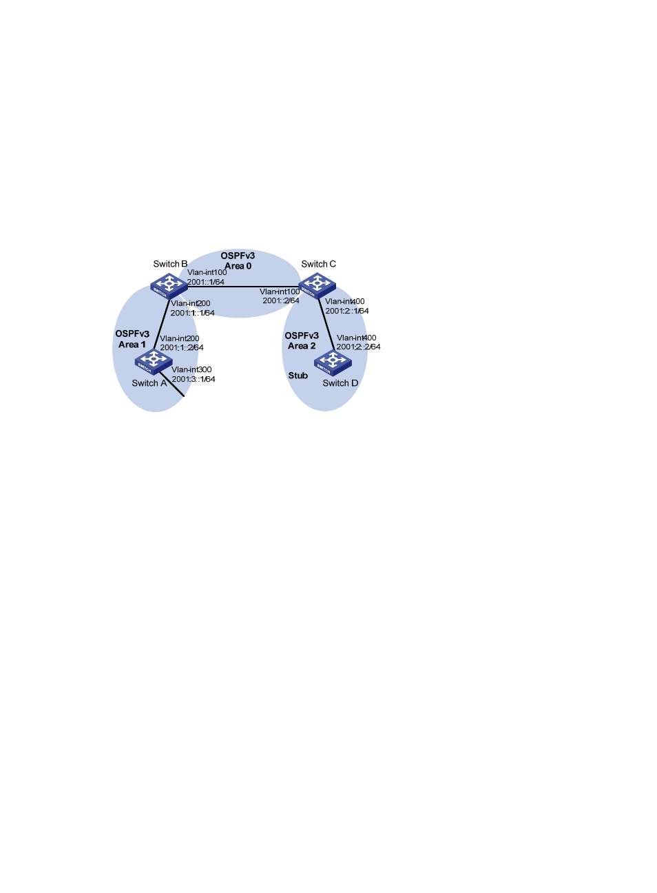
Network requirements
, all switches run OSPFv3. The AS is split into three areas, in which, Switch B and Switch C
act as ABRs to forward routing information between areas.
Configure Area 2 as a stub area in order to reduce LSAs in the area without affecting route reachability.
Figure 106 Network diagram for OSPFv3 area configuration
Configuration procedure
1.
Configure IPv6 addresses for interfaces. (Details not shown)
2.
Configure OSPFv3 basic functions.
# Configure Switch A.
<SwitchA> system-view
[SwitchA] ipv6
[SwitchA] ospfv3
[SwitchA-ospfv3-1] router-id 1.1.1.1
[SwitchA-ospfv3-1] quit
[SwitchA] interface vlan-interface 300
[SwitchA-Vlan-interface300] ospfv3 1 area 1
[SwitchA-Vlan-interface300] quit
[SwitchA] interface vlan-interface 200
[SwitchA-Vlan-interface200] ospfv3 1 area 1
[SwitchA-Vlan-interface200] quit
# Configure Switch B.
<SwitchB> system-view
[SwitchB] ipv6
[SwitchB] ospfv3
[SwitchB-ospf-1] router-id 2.2.2.2
[SwitchB-ospf-1] quit
[SwitchB] interface vlan-interface 100
[SwitchB-Vlan-interface100] ospfv3 1 area 0