Configuring ospf virtual links, Network requirements, Configuration procedure – H3C Technologies H3C S10500 Series Switches User Manual
Page 133
118
[SwitchA] display ospf interface
OSPF Process 1 with Router ID 1.1.1.1
Interfaces
Area: 0.0.0.0
IP Address Type State Cost Pri DR BDR
192.168.1.1 Broadcast DR 1 100 192.168.1.1 192.168.1.3
[SwitchB] display ospf interface
OSPF Process 1 with Router ID 2.2.2.2
Interfaces
Area: 0.0.0.0
IP Address Type State Cost Pri DR BDR
192.168.1.2 Broadcast DROther 1 0 192.168.1.1 192.168.1.3
NOTE:
The interface state
DROther means the interface is not the DR/BDR.
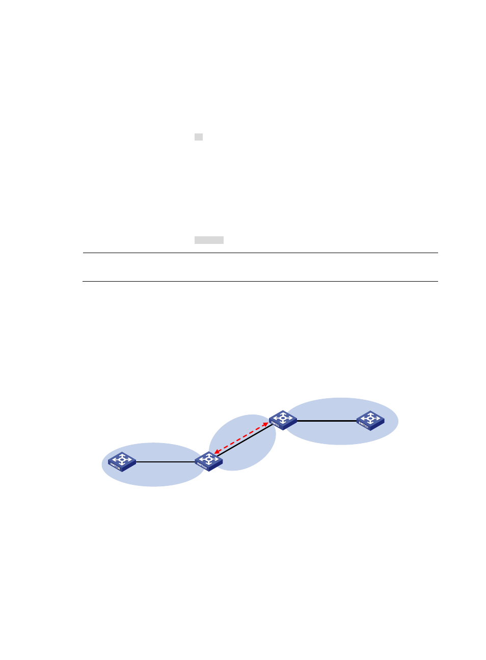
Configuring OSPF virtual links
Network requirements
•
In
, Area 2 has no direct connection to Area 0, and Area 1 acts as the Transit Area to
connect Area 2 to Area 0 via a configured virtual link between Switch B and Switch C.
•
After configuration, Switch B can learn routes to Area 2.
Figure 44 Network diagram for OSPF virtual link configuration
Area 0
Swtich A
Vlan-int300
10.1.1.1/24
Swtich B
Switch C
Switch D
Area 2
Vlan-int300
10.1.1.2/24
Vlan-int100
10.3.1.2/24
Vlan-int100
10.3.1.1/24
Vir
tua
l li
nk
Vlan-int200
10.2.1.1/24
Vlan-int200
10.2.1.2/24
Area 1
Configuration procedure
1.
Configure IP addresses for interfaces. (Details not shown)
2.
Configure OSPF basic functions.
# Configure Switch A.
<SwitchA> system-view
[SwitchA] ospf 1 router-id 1.1.1.1
[SwitchA-ospf-1] area 0
[SwitchA-ospf-1-area-0.0.0.0] network 10.1.1.0 0.0.0.255