Configuring ospf dr election, Network requirements, Configuration procedure – H3C Technologies H3C S10500 Series Switches User Manual
Page 129
114
Routing Tables
Routing for Network
Destination Cost Type NextHop AdvRouter Area
10.2.1.0/24 22 Inter 10.3.1.1 10.3.1.1 0.0.0.2
10.3.1.0/24 10 Transit 10.3.1.2 10.3.1.1 0.0.0.2
10.4.1.0/24 25 Inter 10.3.1.1 10.3.1.1 0.0.0.2
10.5.1.0/24 10 Stub 10.5.1.1 10.5.1.1 0.0.0.2
10.1.1.0/24 12 Inter 10.3.1.1 10.3.1.1 0.0.0.2
Routing for ASEs
Destination Cost Type Tag NextHop AdvRouter
3.1.3.0/24 1 Type2 1 10.3.1.1 10.2.1.1
Total Nets: 6
Intra Area: 2 Inter Area: 3 ASE: 1 NSSA: 0
NOTE:
The output shows that on Switch D an external route imported from the NSSA area.
Configuring OSPF DR election
Network requirements
•
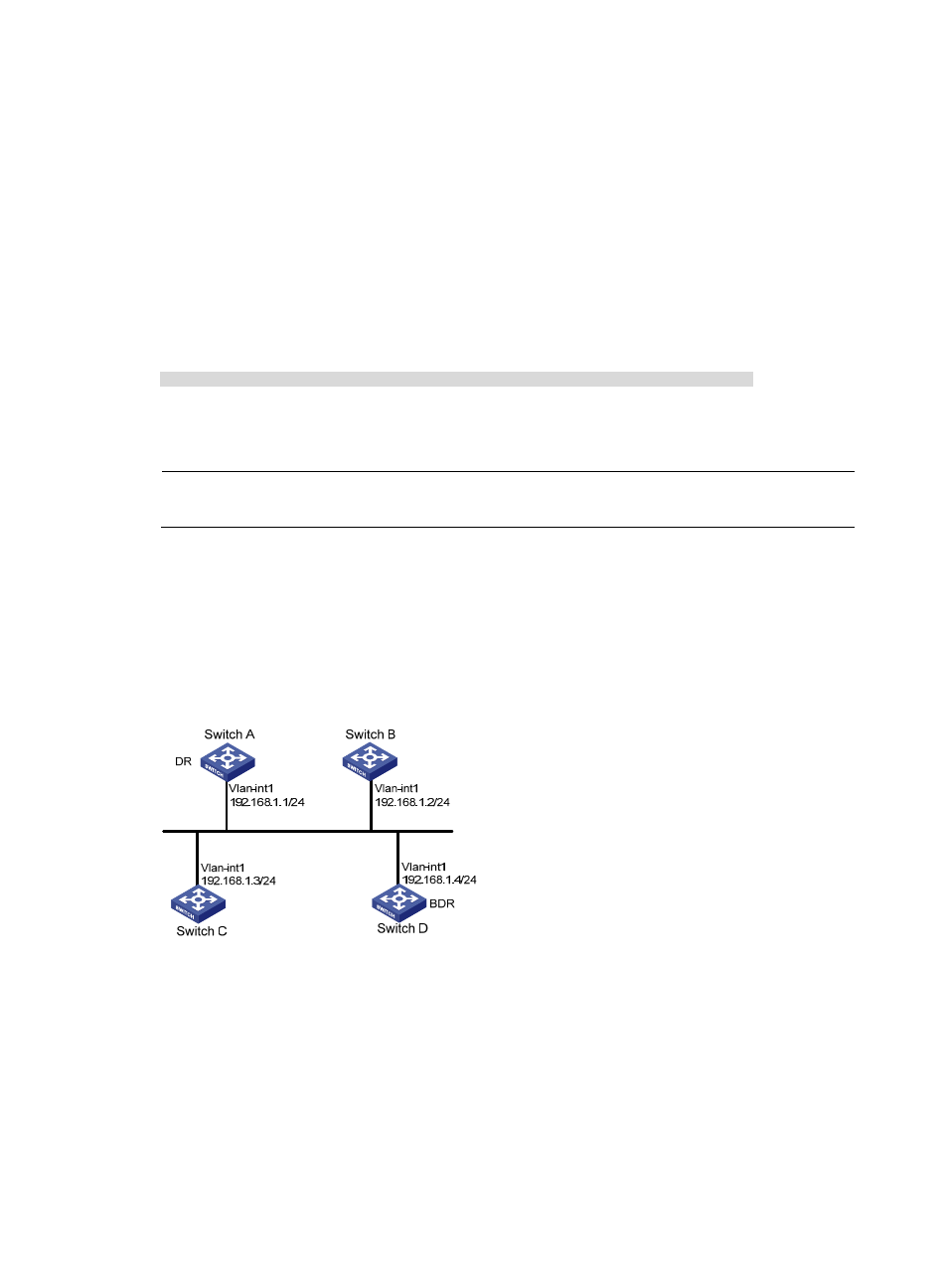
, OSPF Switches A, B, C, and D reside on the same network segment.
•
Configure Switch A as the DR, and configure Switch C as the BDR.
Figure 43 Network diagram for OSPF DR election configuration
Configuration procedure
1.
Configure IP addresses for interfaces. (Details not shown)
2.
Configure OSPF basic functions.
# Configure Switch A.
<SwitchA> system-view
[SwitchA] router id 1.1.1.1
[SwitchA] ospf
[SwitchA-ospf-1] area 0