Network requirements, Configuration procedure – H3C Technologies H3C S10500 Series Switches User Manual
Page 57
42
[SwitchB] acl number 2000
[SwitchB-acl-basic-2000] rule deny source 10.2.1.1 0.0.0.255
[SwitchB-acl-basic-2000] rule permit
[SwitchB-acl-basic-2000] quit
[SwitchB] rip 200
[SwitchB-rip-200] filter-policy 2000 export rip 100
# Display the routing table of Switch C.
[SwitchC] display ip routing-table
Routing Tables: Public
Destinations : 7 Routes : 7
Destination/Mask Proto Pre Cost NextHop Interface
11.1.1.0/24 RIP 100 1 12.3.1.1 Vlan200
12.3.1.0/24 Direct 0 0 12.3.1.2 Vlan200
12.3.1.2/32 Direct 0 0 127.0.0.1 InLoop0
16.4.1.0/24 Direct 0 0 16.4.1.1 Vlan400
16.4.1.1/32 Direct 0 0 127.0.0.1 InLoop0
127.0.0.0/8 Direct 0 0 127.0.0.1 InLoop0
127.0.0.1/32 Direct 0 0 127.0.0.1 InLoop0
Configuring an additional metric for a RIP interface
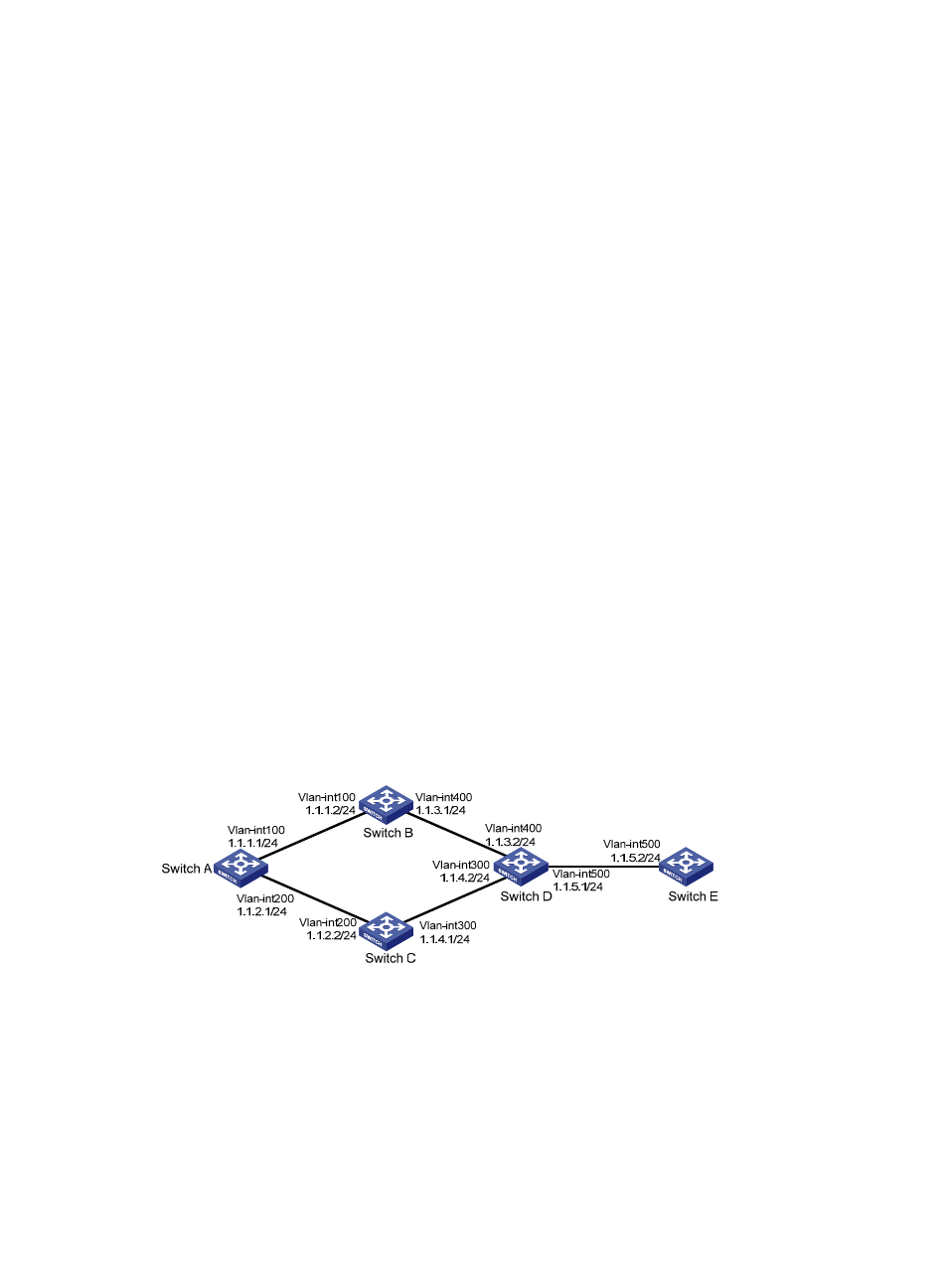
Network requirements
As shown in the following figure:
•
RIP is enabled on all the interfaces of Switch A, Switch B, Switch C, Switch D, and Switch E. The
switches are interconnected through RIPv2.
•
Switch A has two links to Switch D. The link from Switch B to Switch D is more stable than that from
Switch C to Switch D. Configure an additional metric for RIP routes received through VLAN-interface
200 on Switch A so that Switch A prefers the 1.1.5.0/24 network learned from Switch B.
Figure 12 Network diagram for RIP interface additional metric configuration
Configuration procedure
1.
Configure IP addresses for the interfaces. (Details not shown)
2.
Configure RIP basic functions.
# Configure Switch A.
<SwitchA> system-view
[SwitchA] rip 1
[SwitchA-rip-1] network 1.0.0.0