Configuring rip frr, Configuration prerequisites, Configuration procedure – H3C Technologies H3C S10500 Series Switches User Manual
Page 51
36
To do…
Use the command…
Remarks
Enable a RIP process and enter RIP
view
rip [ process-id ] [ vpn-instance
vpn-instance-name ]
––
Configure the maximum number of
RIP packets that can be sent at the
specified interval
output-delay time count count
Optional
By default, an interface sends up to
three RIP packets every 20
milliseconds.
Configuring RIP FRR
NOTE:
•
RIP FRR is only effective for non-recursive RIP routes (that are learned from directly connected
neighbors).
•
Do not use RIP FRR and BFD (for RIP) at the same time; otherwise, RIP FRR may fail to take effect.
When a link in a RIP network fails, the traffic is interrupted until RIP completes routing convergence based
on the new network topology.
You can enable RIP fast reroute (FRR) to reduce traffic recovery time.
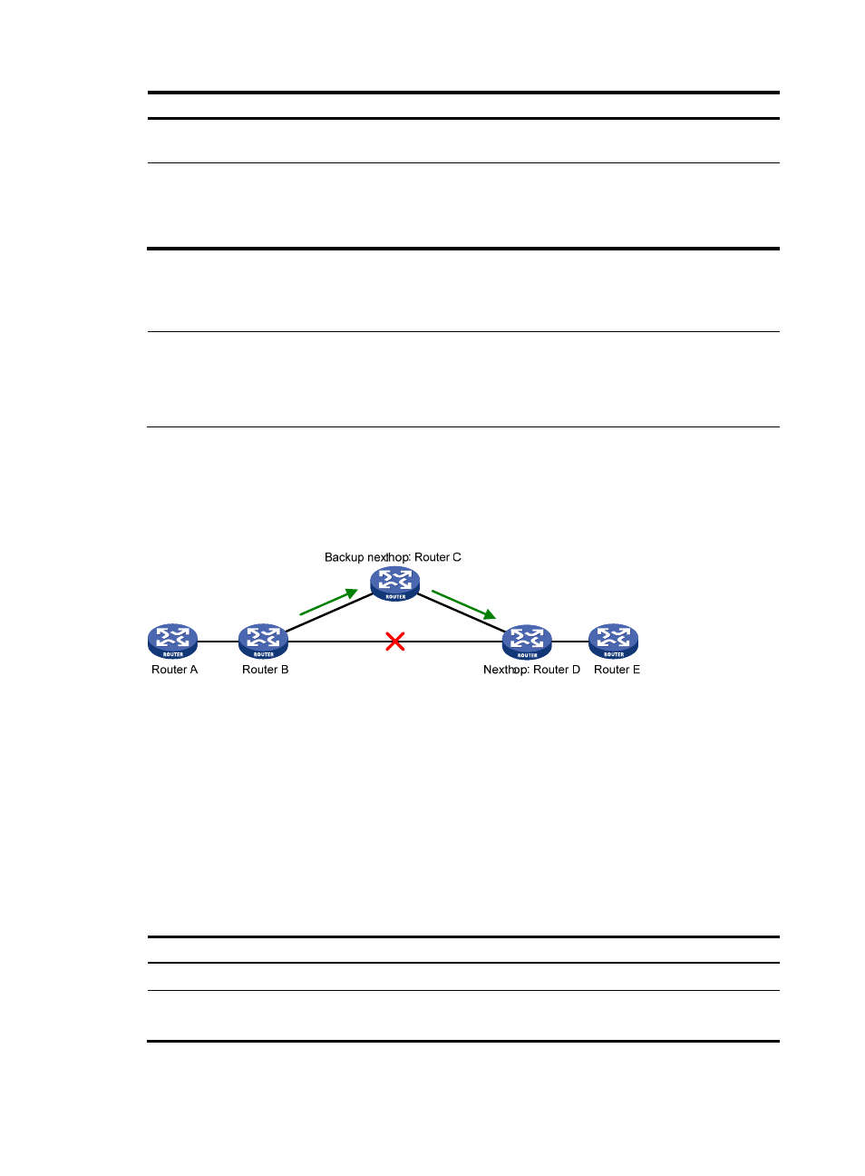
Figure 9 Network diagram for RIP FRR
, after you enable FRR on Router B, RIP designates a backup next hop using a routing policy
when a network failure is detected. Packets are directed to the backup next hop to reduce traffic recovery
time. At the same time, RIP calculates the shortest path based on the new network topology, and forwards
packets over the path after network convergence.
Configuration prerequisites
You need to specify a next hop by using the apply fast-reroute backup-interface command in a routing
policy and reference the routing policy with RIP FRR. For more information about routing policy
configuration, see the chapter “Routing policy configuration.”
Configuration procedure
Follow these steps to configure RIP FRR:
To do…
Use the command…
Remarks
Enter system view
system-view
—
Configure the source address of
echo packets
bfd echo-source-ip ip-address
Required
Not configured by default.