Configuring bfd for ipv6 is-is, Network requirements, Configuration procedure – H3C Technologies H3C S10500 Series Switches User Manual
Page 333
318
Flag : D/L/- Cost : 10
Next Hop : Direct Interface: Vlan300
Destination: 2001:4::1 PrefixLen: 128
Flag : D/L/- Cost : 0
Next Hop : Direct Interface: Loop1
Flags: D-Direct, R-Added to RM, L-Advertised in LSPs, U-Up/Down Bit Set
Configuring BFD for IPv6 IS-IS
Network requirements
•
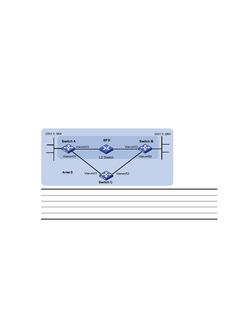
As shown in
, configure IPv6 IS-IS on Switch A, Switch B, and Switch C and configure BFD
over the link Switch A<—>L2 Switch<—>Switch B.
•
After the link between Switch B and the Layer-2 switch fails, BFD can quickly detect the failure and
notify IPv6 IS-IS of the failure. Then Switch A and Switch B communicate through Switch C.
Figure 112 Network diagram for BFD configuration for IPv6 IS-IS
Device
Interface
IPv6 address
Device
Interface
IPv6 address
Switch A
Vlan-int10
2001::1/64
Switch B
Vlan-int10
2001::2/64
Vlan-int11
2001:2::1/64
Vlan-int13
2001:3::2/64
Switch
C
Vlan-int11
2001:2::2/64
Vlan-int13
2001:3::1/64
Configuration procedure
1.
Configure IP addresses for interfaces. (Details not shown)
2.
Configure IPv6 IS-IS.
# Configure Switch A.
<SwitchA> system-view
[SwitchA] ipv6
[SwitchA] isis 1
[SwitchA-isis-1] is-level level-1
[SwitchA-isis-1] network-entity 10.0000.0000.0001.00
[SwitchA-isis-1] ipv6 enable
[SwitchA-isis-1] quit
[SwitchA] interface vlan-interface 10