Network requirements, Configuration procedure – H3C Technologies H3C S10500 Series Switches User Manual
Page 33
18
Public Routing Table : Static
Summary Count : 2
Static Routing table Status : < Active>
Summary Count : 1
Destination/Mask Proto Pre Cost NextHop Interface
120.1.1.0/24 Static 65 0 10.1.1.100 Vlan11
Static Routing table Status : < Inactive>
Summary Count : 1
Destination/Mask Proto Pre Cost NextHop Interface
120.1.1.0/24 Static 60 0 12.1.1.2 Vlan10
BFD for static routes configuration example (indirect session)
Network requirements
As shown in
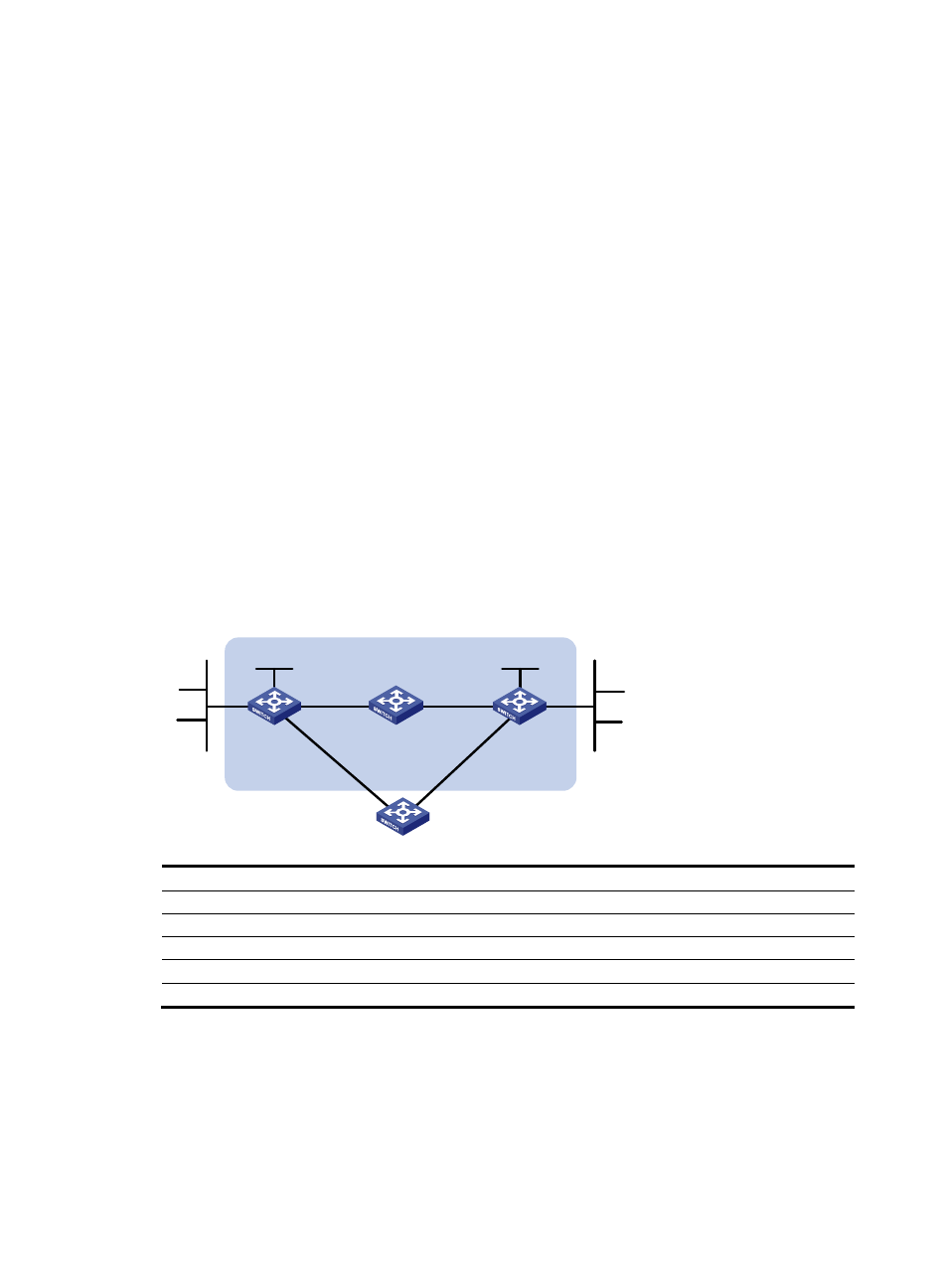
, Switch A has a route to interface Loopback1 (2.2.2.9/32) on Switch B, with
outbound interface VLAN-interface 10. Switch B has a route to interface Loopback1 (1.1.1.9/32) on
Switch A, with outbound interface VLAN-interface 12. Switch D has a route to 1.1.1.9/32, with outbound
interface VLAN-interface 10, and a route to 2.2.2.9/32, with outbound interface VLAN-interface 12.
Configure static routes to subnet 120.1.1.0/24 on Switch A, static routes to subnet 121.1.1.0/24 on Switch
B, and static routes to subnets 120.1.1.0/24 and 121.1.1.0/24 on both Switch C and Switch D. Enable BFD
so that when the link between Switch A and Switch B through Switch D fails, BFD can detect the failure
immediately and Switch A and Switch B can communicate through Switch C.
Figure 5 Network diagram for configuring BFD for static routes (indirect session)
Switch A
Switch B
Switch C
BFD
Vlan-int10
Vlan-
in
t11
Vlan-int11
Vlan-int13
Vlan-
in
t1
3
Vlan-int10
121.1.1.0/24
120.1.1.0/24
Switch D
Vlan-int12
Vlan-int12
Loop1
1.1.1.9/32
Loop1
2.2.2.9/32
Device
Interface
IP address
Device
Interface
IP address
Switch A
Vlan-int10
12.1.1.1/24
Switch B
Vlan-int12
11.1.1.1/24
Vlan-int11
10.1.1.102/24
Vlan-int13
13.1.1.1/24
Loop1
1.1.1.9/32
Loop1
2.2.2.9/32
Switch C
Vlan-int11
10.1.1.100/24
Switch D
Vlan-int10
12.1.1.2/24
Vlan-int13
13.1.1.2/24
Vlan-int12
11.1.1.2/24
Configuration procedure
1.
Configure IP addresses for the interfaces. (Details not shown)
2.
Configure BFD.
# Configure static routes on Switch A and enable BFD control packet mode for the static route through
Switch D.
<SwitchA> system-view