Configuration procedure – H3C Technologies H3C S10500 Series Switches User Manual
Page 249
234
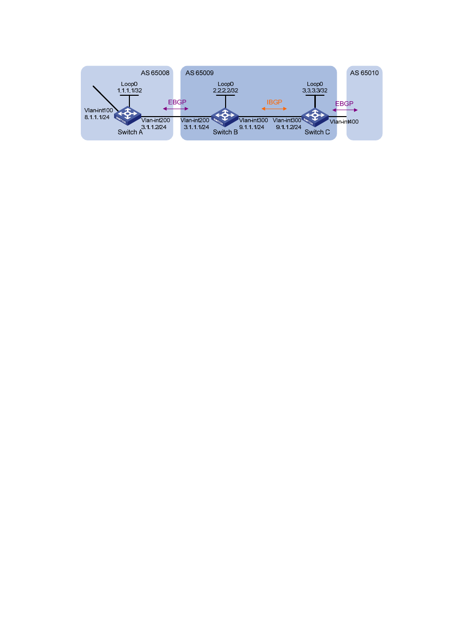
Figure 90 Network diagram for BGP basic configuration
Configuration procedure
1.
Configure IP addresses for interfaces. (Details not shown)
2.
Configure iBGP.
•
To prevent route flapping caused by port state changes, this example uses loopback interfaces to
establish iBGP connections.
•
Because loopback interfaces are virtual interfaces, you need to use the peer connect-interface
command to specify the loopback interface as the source interface for establishing BGP
connections.
•
Enable OSPF in AS 65009 to ensure that Switch B can communicate with Switch C through
loopback interfaces.
# Configure Switch B.
<SwitchB> system-view
[SwitchB] bgp 65009
[SwitchB-bgp] router-id 2.2.2.2
[SwitchB-bgp] peer 3.3.3.3 as-number 65009
[SwitchB-bgp] peer 3.3.3.3 connect-interface loopback 0
[SwitchB-bgp] quit
[SwitchB] ospf 1
[SwitchB-ospf-1] area 0
[SwitchB-ospf-1-area-0.0.0.0] network 2.2.2.2 0.0.0.0
[SwitchB-ospf-1-area-0.0.0.0] network 9.1.1.1 0.0.0.255
[SwitchB-ospf-1-area-0.0.0.0] quit
[SwitchB-ospf-1] quit
# Configure Switch C.
<SwitchC> system-view
[SwitchC] bgp 65009
[SwitchC-bgp] router-id 3.3.3.3
[SwitchC-bgp] peer 2.2.2.2 as-number 65009
[SwitchC-bgp] peer 2.2.2.2 connect-interface loopback 0
[SwitchC-bgp] quit
[SwitchC] ospf 1
[SwitchC-ospf-1] area 0
[SwitchC-ospf-1-area-0.0.0.0] network 3.3.3.3 0.0.0.0
[SwitchC-ospf-1-area-0.0.0.0] network 9.1.1.0 0.0.0.255
[SwitchC-ospf-1-area-0.0.0.0] quit
[SwitchC-ospf-1] quit
[SwitchC] display bgp peer