Configuring rip route redistribution, Network requirements, Configuration procedure – H3C Technologies H3C S10500 Series Switches User Manual
Page 55
40
10.0.0.0/8 192.168.1.2 1 0 RA 50
10.2.1.0/24 192.168.1.2 1 0 RA 16
10.1.1.0/24 192.168.1.2 1 0 RA 16
The output shows that RIPv2 uses classless subnet mask.
NOTE:
RIPv1 routing information has a long aging time, so it will exist until it ages out after RIPv2 is configured.
Configuring RIP route redistribution
Network requirements
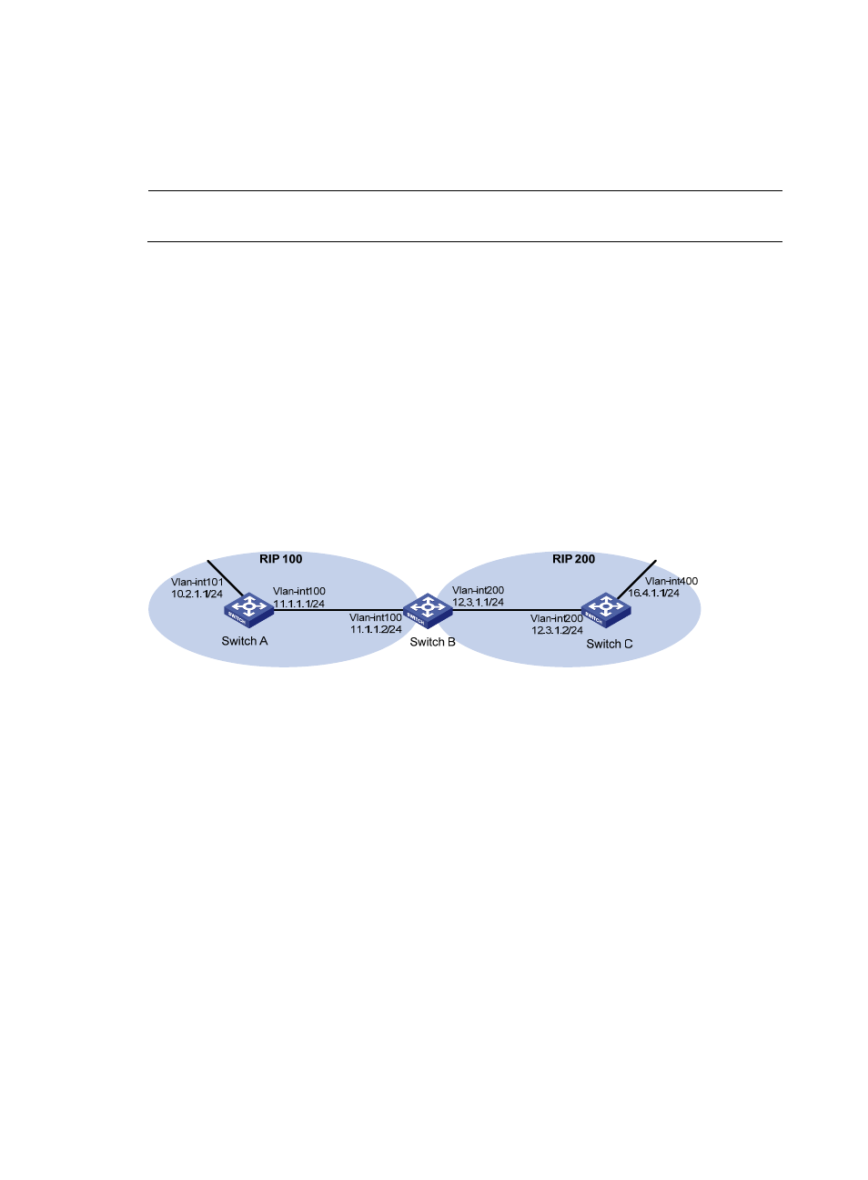
As shown in the following figure:
•
Two RIP processes are running on Switch B, which communicates with Switch A through RIP 100
and with Switch C through RIP 200.
•
Configure route redistribution on Switch B to make RIP 200 redistribute direct routes and routes from
RIP 100. Switch C can then learn routes destined for 10.2.1.0/24 and 11.1.1.0/24, and Switch A
cannot learn routes destined for 12.3.1.0/24 and 16.4.1.0/24.
•
Configure a filtering policy on Switch B to filter out the route 10.2.1.1/24 from RIP 100, making the
route not advertised to Switch C.
Figure 11 Network diagram for RIP route redistribution configuration
Configuration procedure
1.
Configure an IP address for each interface. (Details not shown)
2.
Configure basic RIP functions.
# Enable RIP 100 and specify RIP version 2 on Switch A.
<SwitchA> system-view
[SwitchA] rip 100
[SwitchA-rip-100] network 10.0.0.0
[SwitchA-rip-100] network 11.0.0.0
[SwitchA-rip-100] version 2
[SwitchA-rip-100] undo summary
[SwitchA-rip-100] quit
# Enable RIP 100 and RIP 200 and specify RIP version 2 on Switch B.
<SwitchB> system-view
[SwitchB] rip 100
[SwitchB-rip-100] network 11.0.0.0
[SwitchB-rip-100] version 2
[SwitchB-rip-100] undo summary