Figure b-3 – Verilink C100 (880-502893-001) Product Manual User Manual
Page 100
Sample Applications
B-6
Verilink C100 and C150 T1/FT1 CSU/DSU
6/15/99
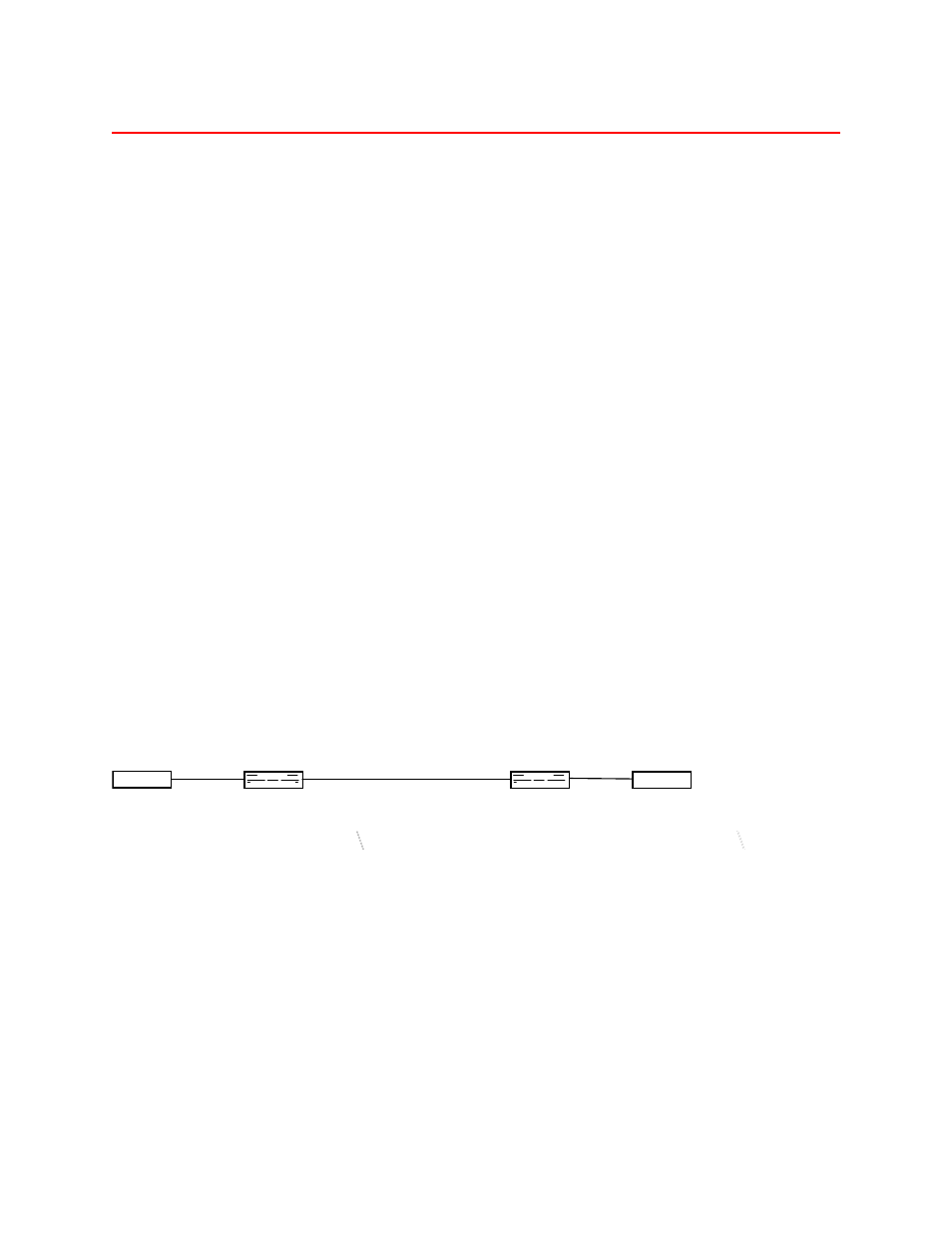
C100/C150 T-1 CSU/DSU Connecting Two Routers in LDM mode
The T-1 CSU/DSU’s can be used a Limited Distance Modems (LDMs)
over customer owned four-wire facilities as shown in
. The
units are used as LDMs connecting two routers at two different
locations which can be up to 6000 feet apart. In this example, the
routers have RS530 interfaces and are operating at 768,000 bps.
Table B-3 illustrates the switch configuration. Because there is no T-1
carrier involved, ones density requirements do not have to be met so
the units can be programmed for Clear channel (all DS0’s set for 64000
bps). Switch pack 2 position 3 should be On at the local and remote
units to invoke Clear channel. When using the CSU/DSU’s as LDMs in
this application, the local unit’s timing is set to Internal with Switch
pack 2 positions 7 Off and 8 On. Timing is left in the default setting of
Network provides timing at the remote.
Switch pack 4 positions 2 and 3 are both Off for RS530 interfaces.
All positions in Switch pack 5 are On and Switch pack 6 positions 1,2, 3
and 4 are On (12 DS0’s times 64000 bps = 768000 bps). Care must be
taken that the selected DS0’s are the same in both units.
The Off position of the DIP switch is the rocker arm of the switch in its
lowest position (down) on the side of the switch closest to the front
panel.
Figure B-3
Using the T-1 C100/C150 CSU/DSUs connecting two routers in LDM mode
C100/C150
Local Site
NI
CI Sync
................
ROUTER
TEL-LINK
T-1 CSU/DSU
NI
................
TEL-LINK
T-1 CSU/DSU
CI Sync
ROUTER
Remote Site
Customer
Four-wire
Facilit
C100/C150
C100/C150