Synchronous channel invert data, Synchronous channel invert external transmit clock, Figure 3-1 – Verilink C100 (880-502893-001) Product Manual User Manual
Page 37: Synchronous channel invert external transmit cloc
Configuration Using the DIP Switches
06/17/97
C100 and C150 T1/FT1 CSU/DSU
3-13
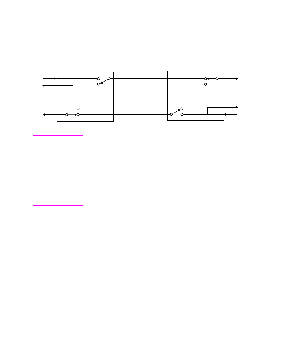
is a block diagram which shows the end-to-end interaction
of Request-To-Send, Carrier Detect and the DS-0 selection.
Figure 3-1
Block diagram of Carrier (Receive Line Signal Detect) Control
Synchronous
Channel Invert Data
Switch pack 4 position 6 determines whether data to and from the
Synchronous Channel is normal or inverted. With position 6 Off, data
on the Synchronous Channel passes normally. With position 6 On, both
the transmit and receive data signals at the local Synchronous Channel
are inverted. By inverting the data, this feature permits certain
protocols such as HDLC, SDLC, etc. to pass over the T-1 facility at
multiples of 64000 bps and meet ones density requirements of the
Network. When using this mode, both the local and remote units must
have this option selected.
Synchronous
Channel Invert
External Transmit
Cloc
Switch pack 4 position 7 determines whether External Transmit Clock
from the Synchronous Channel is normal or inverted. With position 6
Off, the External Transmit Clock on the Synchronous Channel passes
normally. With position 7 On, External Transmit Clock from the local
Synchronous Channel is inverted. This feature is used when the round
trip delay of the Transmit Clock exceeds one half bit time (due to cable
length and higher frequencies). This feature should be tried if sporadic
errors are noticed on the Synchronous Channel.
Synchronous
Channel Internal Or
External Transmit
Cloc
Switch pack 4 position 8 determines whether Internal Clock or
External Transmit Clock is used. With position 8 Off, Internal Transmit
Clock from the T-1 CSU/DSU is provided to the Synchronous
Channel. With position 8 On, External Transmit Clock from the
terminal equipment to the Synchronous Channel. When using this
mode, External Transmit Clock coming from the terminal equipmen
+V (On)
Switched
Continuous
64000
56000
+V (On)
+V (On)
Continuous
Switched
56000
64000
+V (On)
RTS
CTS
CD
CD
CTS
RTS
Local T-1 CSU/DSU
Remote T-1 CSU/DSU