Figure b-4 – Verilink C100 (880-502893-001) Product Manual User Manual
Page 102
Sample Applications
B-8
Verilink C100 and C150 T1/FT1 CSU/DSU
6/15/99
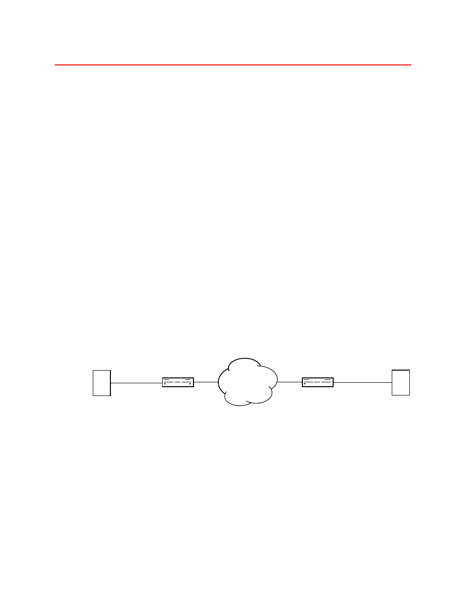
C150 T-1 CSU/DSU connecting two PBXs and converting D4 To ESF
The T-1 CSU/DSU can be used to connect two PBXs together over a T-
1 facility as shown in
. Since some older PBXs don’t support
ESF framing, the CSU/DSU’s can also be used to convert D4 to ESF
framing as described in this example. ESF provides the user with
better diagnostics, reporting and maintenance from the CSU/DSU’s
and the T-1carrier provider. In this mode, the Synchronous channel is
not used.
Table B-4 illustrates the switch configuration. There is very little
change from the factory default selection (all switches Off) in this
application. The only switch setting changes are Switch pack 3
positions 2 and 3 from ESF (Off) to D4 (On) and B8ZS (Off) to AMI
(On) respectively at both the local and remote sites. This sets the DSX1
channel to D4 with AMI encoding at both ends and leaves the
Network Interfaces set to ESF (Switch pack 2 position 1 Off). Since the
DSX1 channel is using all the DS0’s in this application, Switch pack 5,
6, and 7 are all programmed Off.
Timing is left in the default setting of
Network provides timing
with
Switch pack 2 positions 7 and 8 Off since the units are connected to a
carrier-provided T-1 Network.
The Off position of the DIP switch is the rocker arm of the switch in its
lowest position (down) on the side of the switch closest to the front
panel.
Figure B-4
C150 T-1 CSU/DSUs connecting two PBXs over T-1 and converting D4 to ESF
C150 only
P
P
Local Site
ESF NI
D4 CI DSX1
................
TEL-LINK
T1 CSU/DSU
ESF NI
................
TEL-LINK
T1 CSU/DSU
D4 CI DSX1
Remote Site
NETWORK
C150
C150