Console in interface, Console out interface, Table c-5 – Verilink C100 (880-502893-001) Product Manual User Manual
Page 111: Table c-6
Interfaces and Cables
6/15/99
Verilink C100 and C150 T1/FT1 CSU/DSU
C-5
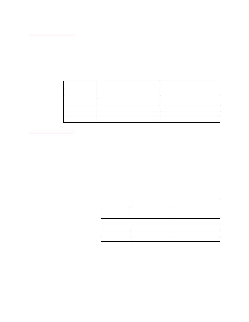
Console IN
Interface
The Console IN Interface is a 6-position modular connector. This
connector is used to connect the console or modem to the T-1
CSU/DSU. The 6-position modular cable with the DB25 male hood
supplied with the unit is connected to the ASCII terminal. The cable
and 25 pin hood are described at the end of this section. The interface
pins on the 6 position modular connector are described as follows:
Table C-5
6-Position Modular Console IN Connector on Rear of Unit
Console OUT
Interface
The Console OUT Interface is a 6-position modular connector. This
connector is used to connect the Verilink T-1 CSU/DSU to another
Verilink T-1 CSU/DSU. Up to eight units may be connected together in
this fashion so that only one console or modem is needed. When
connecting units in this way the DB25 hood to modular connector
provided is only needed on the first T-1 CSU/DSU. To connect
additional T-1 CSU/DSUs, connect Console OUT on the first unit to
Console IN on the second unit using the cable provided. The interface
pins on the 6 position modular connector marked Console OUT are
described as follows.
Table C-6
6-Position Modular Console OUT Connector on Rear of Unit
Pin Number
Signal Name
Direction
1
Received Data
to T-1 CSU/DSU
2
Ground
both ways
3
RLSD or Carrier
to T-1 CSU/DSU
4
Data Terminal Ready
from T-1 CSU/DSU
5
Data Set Ready
to T-1 CSU/DSU
6
Transmitted Data
from T-1 CSU/DSU
Pin Number
Signal Name
Direction
1
Received Data
to next T-1 CSU/DSU
2
Ground
both ways
3
no connection
4
no connection
5
no connection
6
Transmitted Data
from next T-1 CSU/DSU