Rs232/rs530/rs4 22 channel interfaces, Table c-3 – Verilink C100 (880-502893-001) Product Manual User Manual
Page 109
Interfaces and Cables
6/15/99
Verilink C100 and C150 T1/FT1 CSU/DSU
C-3
RS232/RS530/RS4
22 channel
interfaces
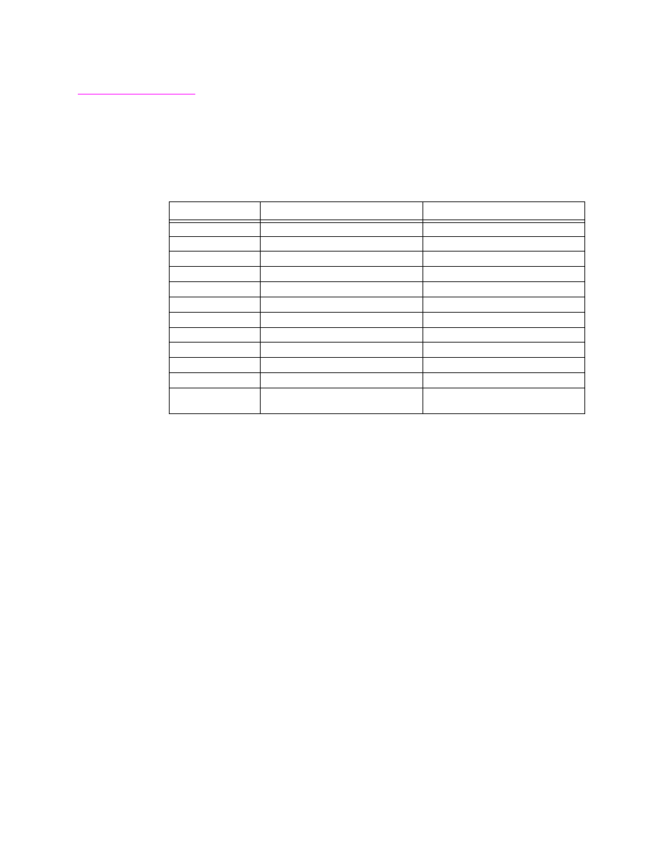
The DB25 pin female on the rear of the unit may be used for either
RS232 or for RS422/RS530 interfaces based on the interface selection
on the DIP switches or console. This interface will appear as a DCE
(modem) to the Customer Equipment. When RS232 is selected, the
interface on the rear of the unit will appear as follows:
Table C-3
DB25 Pin Female Connector Wiring on Rear of Unit When RS232 Is Selected
RS530/422 interface
When RS530/422 interface is selected, the signals on the DB25 pin
connector will also appear as a DCE (modem) to the Custome
Equipment. The interface actually is wired for RS530. A 25 pin to 37
pin RS422 adapter cable (not supplied) must be used for RS422.
wiring diagram for the RS422 cable is included at the end of this
section. When RS530 is selected, the interface on the rear of the unit
will appear as follows:
Pin Number
Signal Name
Direction
1
Shield
both ways
2
Transmitted Data
to T-1 CSU/DSU
3
Received Data
from T-1 CSU/DSU
4
Request to Send
to T-1 CSU/DSU
5
Clear to Send
from T-1 CSU/DSU
6
DCE Ready
from T-1 CSU/DSU
7
Signal Ground
both ways
8
Carrier
from T-1 CSU/DSU
15
Transmit Signal Element Timing
from T-1 CSU/DSU
17
Receiver Signal Element Timing
from T-1 CSU/DSU
20
Data Terminal Ready
to T-1 CSU/DSU
24
DTE Transmit Signal Element
Timing
to T-1 CSU/DSU