Figure b-2, Frame relay service – Verilink C100 (880-502893-001) Product Manual User Manual
Page 98
Sample Applications
B-4
Verilink C100 and C150 T1/FT1 CSU/DSU
6/15/99
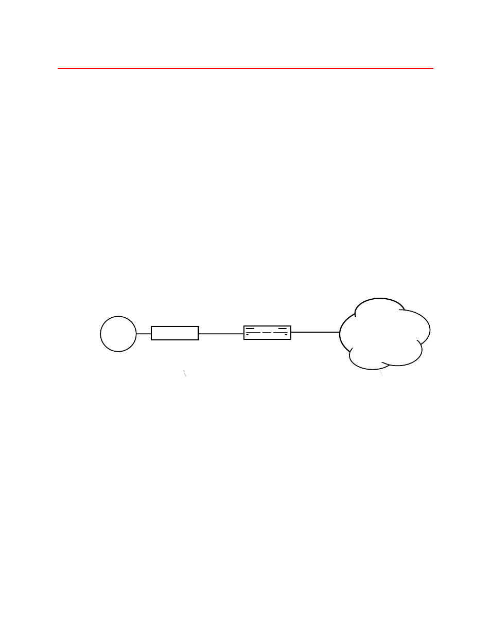
T-1 C100/C150 CSU/DSU Connecting To A Frame Relay Service
shows the T-1 CSU/DSU in a single-ended application
connected to a Frame Relay Service. The Network Interface (NI)
connects to the Fractional T-1 facility and the Customer Interface (CI)
which is 56000 bps with an RS232 interface in this example connects to
the LAN router. The Fractional T-1 facility is ESF framing with B8ZS
encoding.
Table B-2 illustrates the switch configuration. Switch pack 4 position 2
is On and position 3 is Off to select the RS232 interface. Switch pack 5
position 1 is On to allocate 1 DS0 to the Synchronous channel.
Timing is left in the default setting of Network provides timing with
Switch pack 2 positions 7 and 8 Off since the units are connected to a
carrier-provided T-1 Network.
The Off position of the DIP switch is the rocker arm of the switch in its
lowest position (down) on the side of the switch closest to the front
panel.
Figure B-2
Using the C100 T-1 CSU/DSU to connect to a Frame Relay service
C100/C150
Local Site
NI
CI Sync
................
ROUTER
TEL-LINK
T1 CSU/DSU
LAN
FRAME
RELAY
SERVICE
C100/150