Figure 1-9, C150s connecting two sites over t1 -8, Figure 1-10 – Verilink C100 (880-502893-001) Product Manual User Manual
Page 20
Introduction
1-8
Verilink C100 and C150 T1/FT1 CSU/DSU
06/12/97
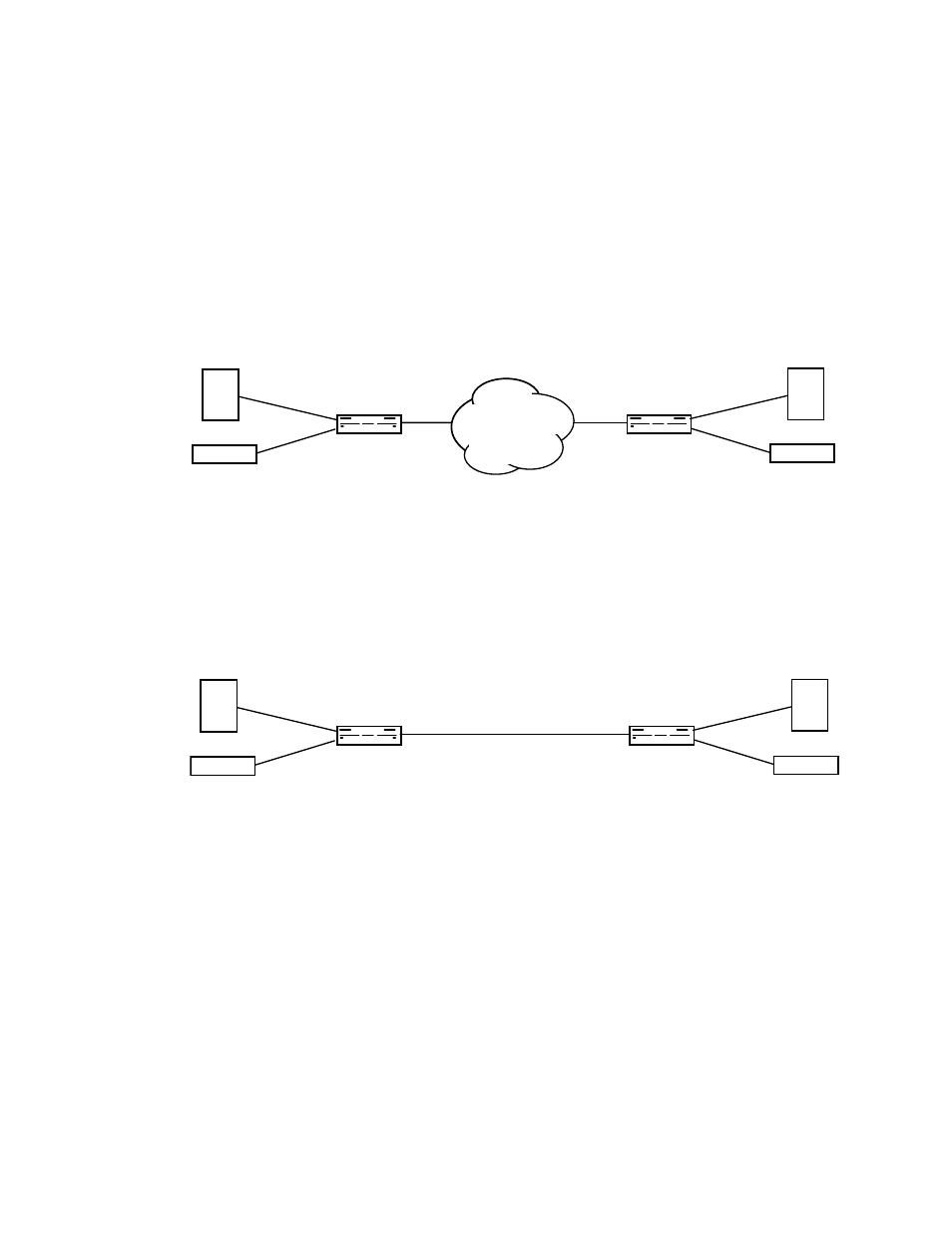
shows a typical application for the C150 CSU/DSU
connecting two sites and using both Customer Interfaces connections
over a T-1 facility. The Network Interface (NI) side of each unit
connects to the T-1 facility and the Customer Interface side of each unit
connects to the customer equipment. In this basic application, the user
is using 224 Kbps (4 DS-0s) for the router to router communication
and the remaining 1120K bps (20 DS-0s) for PBX to PBX voice
communications.
Figure 1-9
C150s connecting two sites over T1
is similar to the application described in
sites
and uses both channels over a T-1 facility. The Network Interface (NI)
side of each unit connects to a customer owned four-wire facility and
the Customer Interface (CI) side of each unit connects to the customer
equipment. In this application, the T-1 CSU/DSUs can be as far as 6000
feet apart.
Figure 1-10 C150s connecting two sites with PBXs over a customer-owned four-wire facility
Local Site
NI
CI DSX
CI Sync
................
ROUTER
TEL-LINK
T-1 CSU/DSU
NI
................
TEL-LINK
T-1 CSU/DSU
PBX
CI DSX
CI Sync
ROUTER
PBX
Remote Site
NETWORK
C150
C150
Local Site
Local Site
NI
CI DSX
CI Sync
................
ROUTER
TEL-LINK
T-1 CSU/DSU
NI
................
TEL-LINK
T-1 CSU/DSU
PBX
CI DSX
CI Sync
ROUTER
PBX
Remote Site
Customer
Four-wire
Facilit
C150
C150