C150 only applications, C150 only applications -7, Figure 1-7 – Verilink C100 (880-502893-001) Product Manual User Manual
Page 19: Figure 1-8, Two c150s connecting pbxs together over t1 -7
Introduction
06/17/97
C100 and C150 T1/FT1 CSU/DSU
1-7
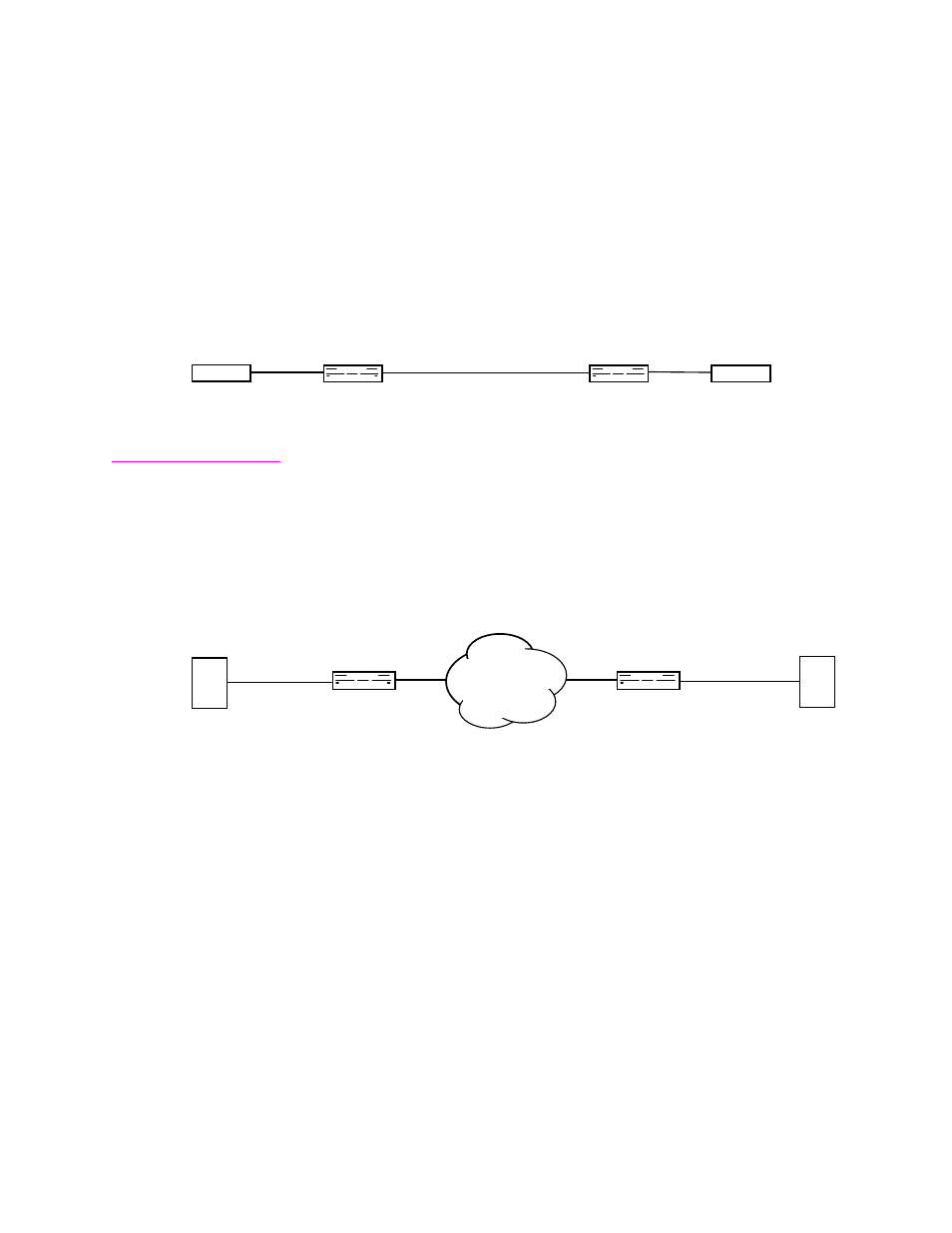
shows a typical application for the CSU/DSU connecting
two sites and using both channels over a T-1 facility. The Network
Interface (NI) side of each unit connects to a customer owned four-
wire facility and the Customer Interface (CI) side of each unit connects
to the customer equipment. In this application, the T-1 CSU/DSUs ca
be as far as 6000 feet apart.
Figure 1-7
C100 or C150s connecting two sites over customer-owned four-wire facility
C150 only
applications
C150 applications can make use of drop-and-insert.
shows
the C150 T-1 CSU/DSU connecting two sites over a T-1 facility in the
second of two very basic applications. The Network Interface (NI) side
of each unit connects to the T-1 service and the Customer Interface (CI)
DSX-1 interface of each unit connects to the customer PBX.
Figure 1-8
Two C150s connecting PBXs together over T1
Local Site
NI
CI Sync
................
ROUTER
TEL-LINK
T-1 CSU/DSU
NI
................
TEL-LINK
T-1 CSU/DSU
CI Sync
ROUTER
Remote Site
Customer
Four-wire
Facilit
C100/150
C100/150
PBX
PBX
Local Site
NI
CI DSX1
................
TEL-LINK
T-1 CSU/DSU
NI
................
TEL-LINK
T-1 CSU/DSU
CI DSX1
Remote Site
NETWORK
C150
C150