H3-08 terminal a2 signal level – Yaskawa iQpump Drive User Manual User Manual
Page 110
5.1 iQpump Basic Programming Parameters
110
YASKAWA TM.iQp.01 iQpump Drive User Manual
Figure 5.20
Figure 5.36 Output Frequency with Reduced Bias Setting
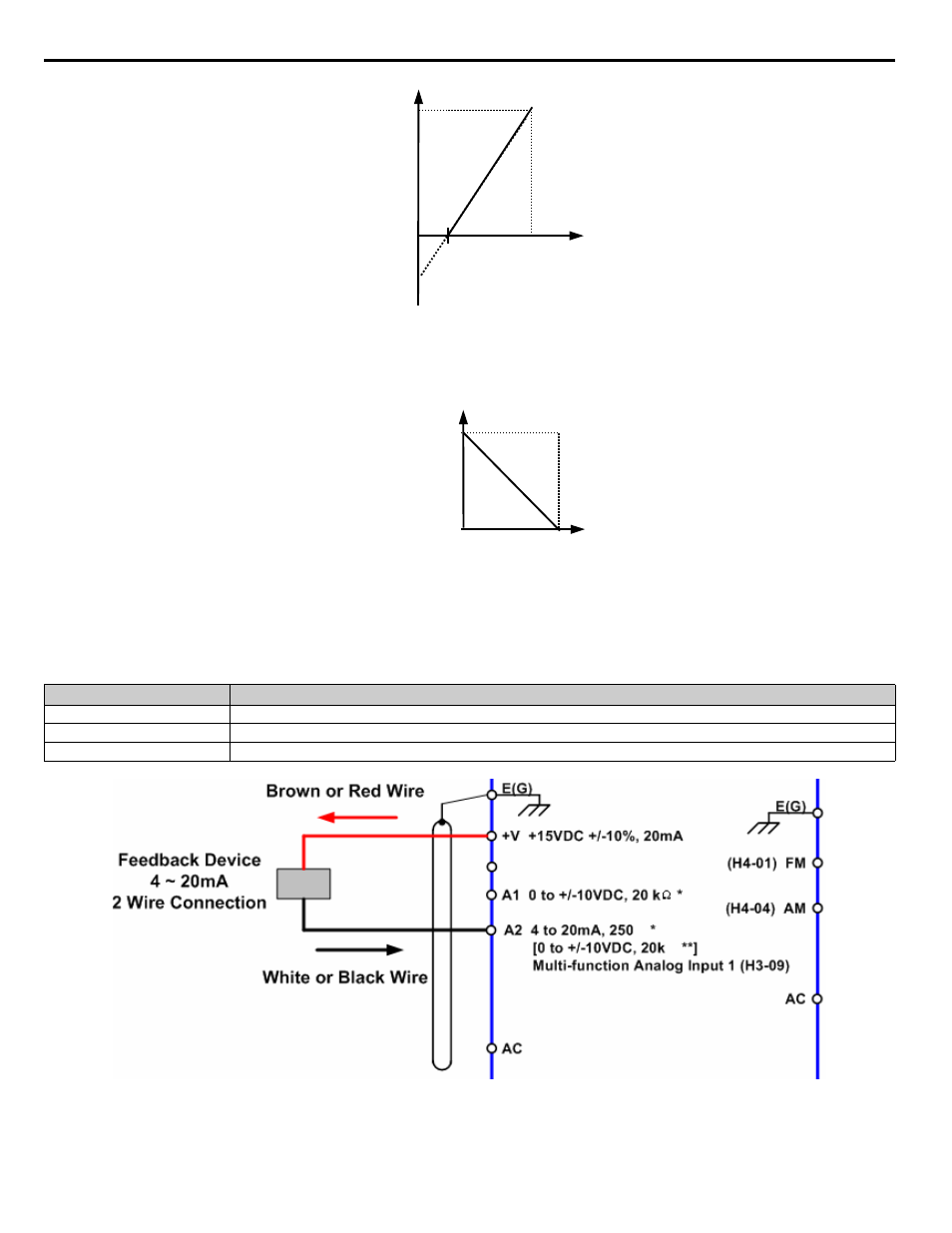
As a further example, for an inverse-acting speed command, set the bias = 100% and the gain = 0%. The minimum analog input level (0
Vdc or 4 mA) will produce a 100% speed command and the maximum analog input level (10 Vdc or 20 mA) will produce a 0% speed
command.
Figure 5.21
Figure 5.37 Output Frequency with Inverted Gain and Bias Settings
■
H3-08 Terminal A2 Signal Level
Figure 5.22
Figure 5.38 Connection of a 2-Wire 4~20 mA Feedback Device (H3-08 = 2)
Setting
Description
0
0 - 10 Vdc
2
4 - 20 mA (factory default)
3
0 - 20 mA
0V
4mA
10V
20mA
Gain = 100%
Bias = -25%
O
ut
put
F
req
ue
ncy
Analog Input Level
2.5V
8mA
Analog Input Signal
20mA
4mA
0V
10V
Gain = 100%
Bias = 0%
Out
put
F
req
uen
cy
Analog Input Level
Analog Input Signal
Bias
Gain