Yaskawa iQpump Drive User Manual User Manual
Page 95
5.1 iQpump Basic Programming Parameters
YASKAWA TM.iQp.01 iQpump Drive User Manual
95
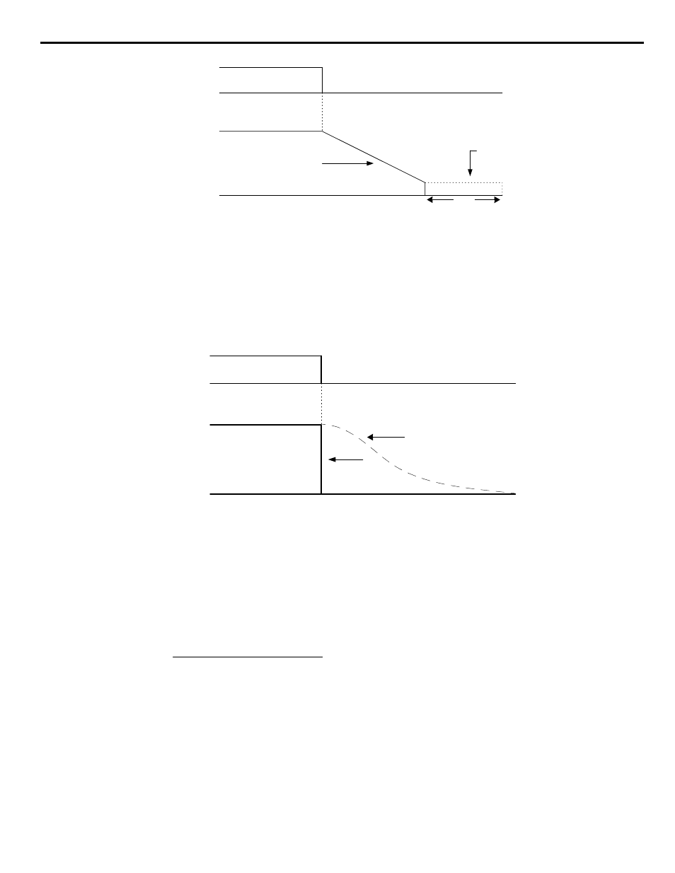
Figure 5.7
Figure 5.9 Deceleration to Stop
The actual deceleration time can be determined by the following formula.
If S-Curve characteristics are specified by the iQpump drive programming, they will add to the total time to stop.
1: Coast to stop: When the Run command is removed, the iQpump drive will turn off its output and the motor will coast (uncontrolled
deceleration). The friction of the driven equipment will eventually overcome any residual inertia of the system and the rotation will stop.
Figure 5.8
Figure 5.10 Coast to Stop
Important: After a stop is initiated, a subsequent Run commands input before the Minimum Baseblock Time (L2-03) has expired, will
be ignored.
2: DCInj to Stop: When the Run command is removed, the iQpump drive will Baseblock (turn off its output) for the Minimum
Baseblock Time (L2-03). Once the Minimum Baseblock Time has expired, the iQpump drive will inject DC current into the motor
windings to lock the motor shaft. The stopping time will be reduced as compared to Coast to Stop. The level of DC Injection current is set
by parameter b2-02 (50% Default). The DC Injection brake time is determined by the set value in b2-04 and the output frequency at the
time the Run command is removed.
ON
OFF
Run Command
Output Frequency
Deceleration Time (C1-02)
DC Injection Brake
100 %
0 %
TIME
| b2-04 |
b2-01
(CLOSED)
(OPEN)
Time to Stop
Output Freq. at time of stop command
Maximum Frequency (E1-04)
------------------------------------------------------------------------------------------- Setting of active Decel Time (C1-02 or C1-04)
×
=
ON
OFF
Run Command
Output Frequency
Drive Output Frequency Interrupted
100 %
0 %
TIME
Motor Speed
(CLOSED)
(OPEN)
04)
-
(E1
Frequency
Maximum
Frequency
Output
10
04)
-
(b2
Time
Brake
Injection
DC
×
×
=