Yaskawa iQpump Drive User Manual User Manual
Page 37
2.2 Wiring Main Circuit Terminals
YASKAWA TM.iQp.01 iQpump Drive User Manual
37
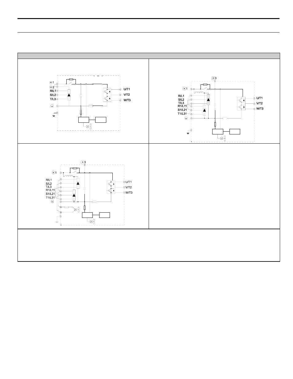
◆ Main Circuit Configurations 208-240 VAC
The 208-240 VAC main circuit configurations of the iQpump drive are shown in
.
Table 2.4 iQpump Drive Main Circuit Configurations
208-240 VAC
—
Note: 1. Input fuses or molded case circuit breakers are required for proper branch circuit protection for all iQpump drives. Failure
to use recommended fuses/circuit breakers (See
) may result in damage to the wiring, iQpump drive and/or
personal injury.
2. Control power is supplied internally from the main circuit DC power supply for all iQpump drives.
3. Consult your Yaskawa representative before using 12-pulse rectification.
Power
supply
Control
circuits
{
1
Note
CIMR-_ _ _ 20P4 to 2018
(1/2 Hp to 25 Hp)
Power
supply
Control
circuits
{
Notes
1 & 3
CIMR-_ _ _ 2022 and 2030
(30 Hp to 40Hp)
CIMR-_ _ _ 2037 to 2110
(50 Hp to 150 Hp)
Power
supply
Control
circuits
{
Notes
1 & 3