D.4 modbus self-diagnosis, Modbus self-diagnosis – Yaskawa iQpump Drive User Manual User Manual
Page 219
D.4 Modbus Self-Diagnosis
YASKAWA
TM.iQp.01 iQpump Drive User Manual
219
D.4 Modbus Self-Diagnosis
The iQpump drive has a built-in function for self-diagnosing the operations of serial communication interface circuits. The self-diagnosis
function connects the communication parts of the send and receive terminals, receives the data sent by the iQpump drive, and checks if
communication is being performed normally.
Perform the self-diagnosis function using the following procedure.
1. Turn ON the power supply to the iQpump drive, and set parameter H1-05 (Terminal S7 Function Selection) to 67 (Comm Test Mode).
2. Turn OFF the power supply to the iQpump drive.
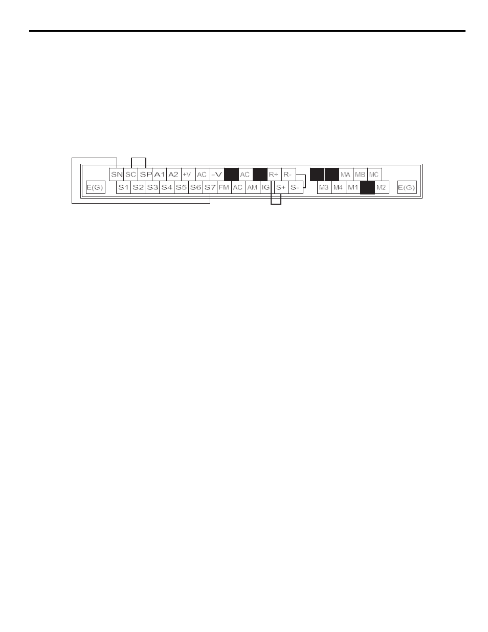
3. Perform wiring according to the following diagram while the power supply is turned OFF.
4. Turn ON the terminating resistance. (Turn ON pin 1 on DIP switch 1.)
5. Turn ON the power supply to the iQpump drive again.
Figure D.8 Communication Terminal Connection for Self -Diagnosis Function
6. During normal self-diagnostic operation, the Digital Operator displays the frequency reference value. If an error occurs, a CE (Modbus
communication error) alarm will be displayed on the Digital Operator, the fault contact output will be turned ON, and the iQpump
drive operation ready signal will be turned OFF.