Yaskawa iQpump Drive User Manual User Manual
Page 187
YASKAWA
TM.iQp.01 iQpump Drive User Manual
187
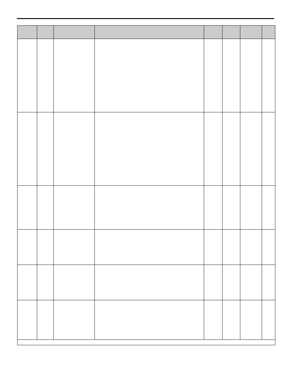
P3-09
061CH
Pump 2 Frequency
Shutdown Level
P2 Freq. Shd Lvl
Sets the level used for multiplex pumping operation. Parameter is
active when P3-01 = 0 or P3-01 = 2 is selected.
P3-01=0:
When the output frequency falls below the level
programmed in P3-09 for a time specified in P3-06 and a total of 2
pumps are running, the last pump (Pump 2) that was brought online
will be shutdown by means of a multi-function digital output opening
(H2-XX = 40, 41).
P3-01=1:
Not Used.
P3-01=2:
When the output frequency falls below the level
programmed in P3-09 and a total of 2 pumps are running and the delta
feedback (feedback minus setpoint) has exceeded the level
programmed in P3-05 for a time specified in P3-06, the last pump
(Pump 2) that was brought online will be shutdown by means of a
multi-function digital output opening (H2-XX = 40, 41).
0.0 to
120.0
35.0 Hz Programming
153
P3-10
061DH
Pump 3 Frequency
Shutdown Level
P3 Freq. Shd Lvl
Sets the level used for multiplex pumping operation. Parameter is
active when P3-01 = 0 or P3-01 = 2 is selected.
PE-01=0:
When the output frequency falls below the level
programmed in P3-10 for a time specified in P3-06 and a total of 3
pumps are running, the last pump (Pump 3) that was brought online
will be shutdown by means of a multi-function digital output opening
(H2-XX = 40, 41).
P3-01=1:
Not Used.
P3-01=2:
When the output frequency falls below the level
programmed in P3-10 and a total of 3pumps are running and the delta
feedback (feedback minus setpoint) has exceeded the level
programmed in P3-05 for a time specified in P3-06, the last pump
(Pump 3) that was brought online will be shutdown by means of a
multi-function digital output opening (H2-XX = 40, 41).
0.0 to
120.00
35.0 Hz Programming
153
P3-11
0110H
Multiplex Stabilization
Time
M-Stabilize Time
Sets the time used to stabilize system when a pump is added (brought
online) or shutdown during multiplex operation. When a pump is
added, the stabilize timer temporarily disables the lead/lag
functionality for the programmed time to prevent pump cycling.
Note:
This function only active in the multiplex mode when P1-01 is
greater than 0.
During the stabilization time, the pump protection and lead-lag control
is suspended.
0 to 3600
2 sec
Programming
154
P3-12
0111H
Delta Setpoint Feedback
Acc/Dec Changeover
SP ACC/DEC Hyst.
Sets the level when the acceleration and deceleration times change over
to the values programmed in C1-05 and C1-06 respectively. This
function will activate when the difference between the delta setpoint
and feedback are within the level programmed in P3-12. This function
is used to improve the pump regulation.A value of 0 disables this
function.
0.0 to
6000.0
(system
units P1-
02)
0.0
(system
units P1-
02)
Programming
155
P3-13
0112H
Friction compensation
start Frequency
Fric. Comp. Lvl
Sets the level when the setpoint will be adjusted to compensate for the
friction losses. This function will activate when the output frequency
rises above the level programmed in P3-13. The maximum
compensation at maximum output frequency (E1-04) is specified by
maximum setpoint frequency (P2-10).
Note:
This function is only active in simplex mode when P1-01 = 0.
0.0 to
120.0
0.0 Hz
Programming
156
P3-14
0113H
Maximum Friction
Increase at Maximum
Frequency
Friction Inc.
Sets the maximum setpoint friction compensation at maximum output
frequency (E1-04). This function is a linear calculation with P3-13 as
its starting frequency.
Example: P3-13 = 30.0 Hz, P3-14 = 10.0 PSI, output frequency = 45.0
Hz and maximum frequency = 60.0 Hz
Setpoint Increase = (45-30 Hz) x 10 PSI / (60 Hz – 30 Hz)
≥ 5.0PSI
Note:
This function is only active in simplex mode when P1-01 = 0.
0.0 to
6000.0
(system
units P1-
02)
0.0
(system
units P1-
02)
Programming
156
Denotes that parameter can be changed when the Drive is running.
Parameter
No.
Modbus
Address
Parameter Name
Digital Operator
Display
Description
Setting
Range
Factory
Setting
Menu
Location
Page
No.