Yaskawa iQpump Drive User Manual User Manual
Page 93
5.1 iQpump Basic Programming Parameters
YASKAWA TM.iQp.01 iQpump Drive User Manual
93
iQpump command register number: 0001
Stop Command:
Transmit value of 0000 (16 bit) to iQpump command address.
Start Command:
Transmit value of 0001 (16 bit) to iQpump command address.
Reset Command:
Transmit value of 0008 (16 bit) to iQpump command address.
If the Run command input is determined by a network communications option PCB: b1-02 = “3: Option PCB,” and initiate the Run
command through the available network communications option PCB listed below. The Installation Guides (IG) and Technical Manuals
(TM) are available at
http://iQpump.yaskawa.com
.
The iQpump Controller allows for monitoring, diagnostics and control using any of the following communication option cards:
• Profibus DP Option Card CM061 Manual: IG.AFD.12
• DeviceNet Option Card CM05X Manual: IG.AFD.14
• Modbus Plus Option Card CM071 Manual: IG.AFD.17
• Modbus TCP/IP Option Card CM090 Manual: IG.AFD.25
• EtherNet/IP Option Card CM092 Manual: IG.AFD.26
Note: Refer to the
communication card instruction manual
or consult factory for installation and operation instructions.
■
Start/Stop from Comm. Option Card (Parameter b1-01 = 3):
The iQpump Controller allows for the Setpoint reference to be set via any of the following communication option cards:
■
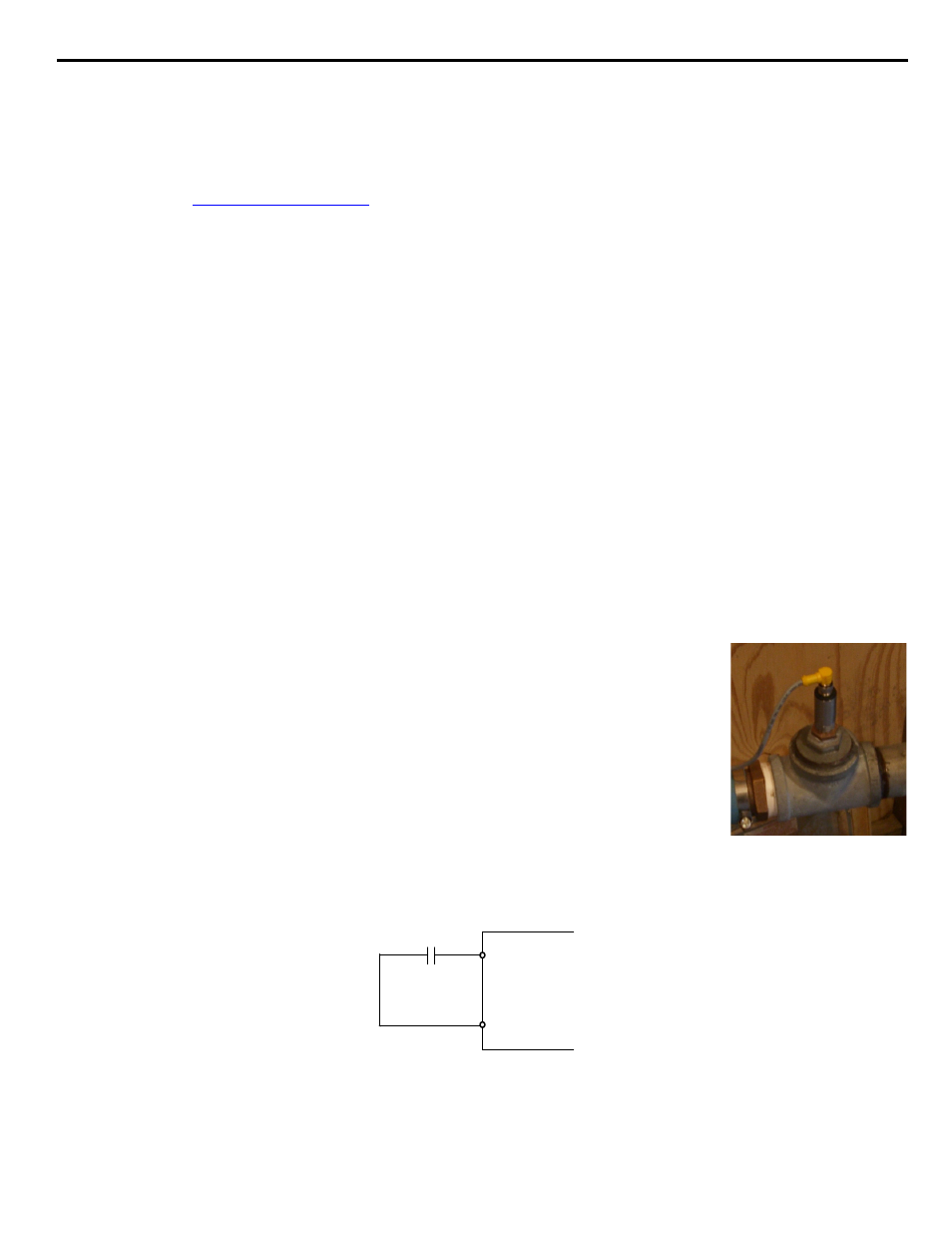
Feedback Device
The iQpump Controller requires a feedback device (e.g. Pressure transducer, flow meter, etc.) to perform automatic system regulation.
Any analog 0~10V or 4-20mA feedback device can be used in combination with the iQpump controller.
Connecting Your Feedback Device to the iQpump Controller
Note: The factory default setting for the iQpump controller is 4~20mA feedback device connected to
analog input A2.
To successfully operate the iQpump drive remotely, an external run command must be received by the
iQpump drive. Parameter b1-02 specifies from where the run command will be accepted.
Although the Run Source and the Reference Source (b1-01) are normally taken from the same source (e.g.
digital operator, terminals or serial communication), this is not always the case.
To issue a run command from the digital operator: Set b1-02 = “0: Operator,” and use the HAND and
OFF buttons to start and stop the iQpump drive.
To issue the run command from the terminals: Set b1-02 = “1: Terminals,” and select between 2-wire
and 3-wire control operation by doing the following:
2-Wire Control The factory default setting is for 2-wire operation. In the 2-wire configuration a closure between S1 and SN will be
interpreted as a Forward Run command by the iQpump drive.
Figure 5.6
Figure 5.7 2-Wire Control
3-Wire Control When any of the multi-function digital input parameters, H1-01 through H1-05, is set to 0, terminals S1 and S2 become
Run and Stop, respectively. The multi-function digital input that was set to 0 will function as a Forward/Reverse input for the iQpump
• Profibus DP Option Card CM061
Manual: IG.AFD.12
• DeviceNet Option Card CM05X
Manual: IG.AFD.14
• Modbus Plus Option Card CM071
Manual: IG.AFD.17
• Modbus TCP/IP Option Card CM090
Manual: IG.AFD.25
• EtherNet/IP Option Card CM092
Manual: IG.AFD.26
S1
S2
SN
FWD Run/Stop
REV Run/Stop
2 wire control