How create a virtual crosspoint, Routers – Grass Valley NV9000-SE v.3.0 User Manual
Page 124
104
Rev 3.0 • 25 Mar 10
7. Routers
Managing Virtual Crosspoints
Virtual crosspoints merely simulate re-entry. No actual re-entry takes place. This means that it is
possible to have as many multiple levels of indirection as desired. In other words, with virtual cros-
spoints (1) there is no physical connection from an output to an input, (2) there is no delay as with
physical re-entry, and (3) virtual output N is coupled only with virtual input N, unlike physical re-
entry where the physical output can be connected to any physical input.
Although complicated, there are several benefits to virtual crosspoints:
• Multiple-destination takes (monitoring, for instance).
• Controlling the device names that appear on the display of a control panel.
• Concealing implementation details from the operator. For example, the normal route could be
be changed to another source and bars could be routed to the virtual output. This would indicate
to anyone monitoring the virtual re-entry source that they are not allowed to view this particular
program, and the private source can be routed directly to LATX PHY.
S
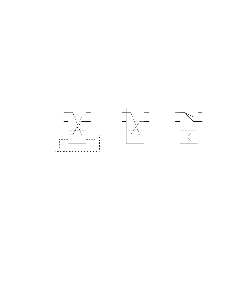
Example: The following illustrates a simple virtual route.
In the example above, virtual input 1 is named LATX and NET1 and NET2 are satellite feeds.
‘LATX PHY’ is the physical output feeding LATX, and MON is the studio monitor. An opera-
tor could route NET1 to LATX or NET2 to LATX and MON in a single take (if the studio mon-
itor is routed to LATX at V1).
Virtual crosspoints exist on a router and apply to each of the physical level(s) of that router. If vir-
tual crosspoints exist on one router, it is likely that you will want to have corresponding virtual
crosspoints on other routers in your system. For example, if your SDI router has 4 virtual cross-
points, your AES router might require 16 virtual crosspoints and your machine control router might
require 4 virtual crosspoints.
How Create a Virtual Crosspoint
1 Launch NV9000-SE. (See
Launching and Exiting the Application
2 From the Navigation area, select the ‘Configuration’ pane and then ‘Routers’. The ‘Routers’
page displays, as shown in Figure 7-35.
To narrow the list of routers that display, enter the first characters of a router name in the ‘Name
Filter’ field. The list is automatically reduced to display only routers matching that character
string.
Or
A
LATX PHY
MON
LATX
V2
NET1
NET2
LATX
V2
A
LATX
MON
NET1
NET2
As the admin sees it
As the software executes it
NET1
NET2
LATX
As the operator sees it
MON
A
LATX
BARS
PRIVATE