Control panels – Grass Valley NV9000-SE v.3.0 User Manual
Page 359
NV9000-SE Utilities • User’s Guide
339
11. Control Panels
Defining General Purpose I/O (GPIO) Connections
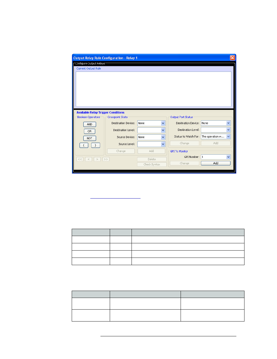
2 In the ‘Outputs’ section, click on any of the four
OUTPUT
buttons to select it. The ‘Output Relay
Rule Configuration’ window appears:
Figure 11-42. Output Relay Rule Configuration Window
Using the “Output Relay Rule Configuration’ window, a Boolean expression can be created
using source destinations, port status, and GPI status. For more information on Boolean expres-
sions, see
3 In the ‘Boolean Operators’ section, click the button matching the Boolean operator you want.
4 In the ‘Crosspoint State’ section, select destination and source information for the output con-
nector from the drop-down lists and click
Add
. (If you are updating existing information, click
Change
.)
5 In the ‘Output Port Status’ section, select status information to be monitored for the output con-
nector from the drop-down lists and click
Add
. (If you are updating existing information, click
Change
.)
Field
Option
Description
Destination Device
‹device›
The device to which the signal through that connector is sent.
Destination Level
‹level›
The signal level for the destination device.
Source Device
‹device›
The device from which the signal is being received.
Source Level
‹level›
The signal level for the source device.
Field
Option
Description
Destination Device
‹device›
The device to which the signal
through that connector is sent.
Destination Level
‹level›
The signal level for the destination
device.