Path contours - polar coordinates -28, 5 path contours - polar coordinates, 0x y – HEIDENHAIN TNC 360 ISO Programming User Manual
Page 111
5-28
5
Programming Tool Movements
TNC 360
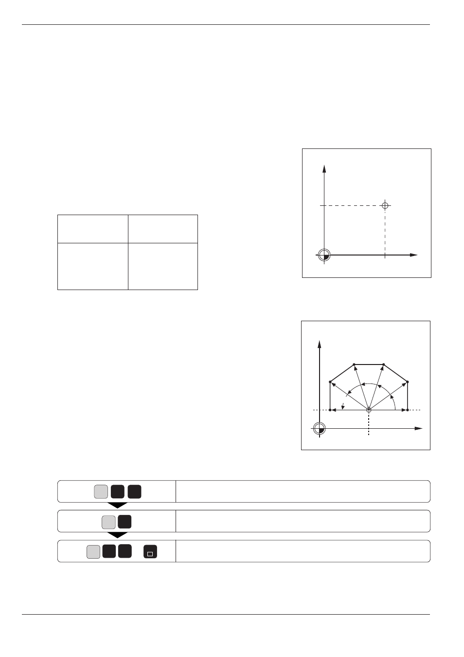
Fig. 5.34:
The pole is entered as circle
center
Fig. 5.35:
Contour consisting of straight
lines
with polar coordinates
G
1
0
R
5
3
H
0
X
Y
H
R
J
I
G91 H
G91 H
G91 H
G91 H
X
Y
Pol
J
I
Working plane
XY
YZ
ZX
POLE
I, J
J, K
K, I
END
5.5 Path Contours - Polar Coordinates
Polar coordinates are useful for programming:
• Positions on circular arcs
• Positions from workpiece drawings showing
angular dimensions
Section 1.2 "Fundamentals of NC" (see page 1-8)
provides a detailed description of polar coordinates.
Polar coordinate origin: Pole I, J, K
You can define the pole anywhere in the program before the blocks
containing polar coordinates. Enter the pole in Cartesian coordinates as a
circle center in a I, J, K block. A pole definition remains effective until a
new pole is defined. The designation of the pole is derived from its
position in the working plane.
You can define the last programmed position as POLE by entering G29.
Straight line at rapid traverse G10
Straight line with feed rate G11 F ...
• You can enter any value from –360° to +360° for H.
• Enter the algebraic sign for H relative to the angle reference axis:
For an angle from the reference axis counterclockwise to R: H>0
For an angle from the reference axis clockwise to R: H<0
Straight line with polar coordinates at rapid traverse.
Enter the radius from the pole to the straight line end point, for
example PR = 5 mm.
Enter the angle from the angle reference axis to R, for example
H = 30°.
Resulting NC block: G10 R5 H30 *