Rs-232-c/v.24 interface -3 – HEIDENHAIN TNC 360 ISO Programming User Manual
Page 194
9-3
TNC 360
9
External Data Transfer
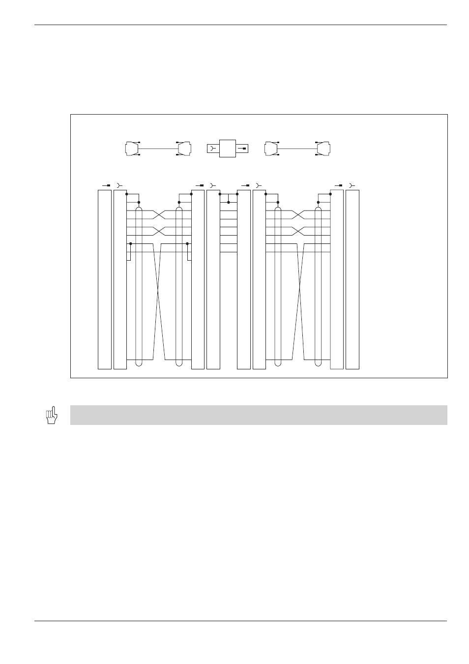
Fig. 9.2:
Pin layout of the RS-232-C/V.24 interface for HEIDENHAIN devices
Id.-Nr. 242 869 01
HEIDENHAIN
standard cable
3 m
Id.-Nr. 239 760..
HEIDENHAIN
connecting cable
max. 17 m
Id.-Nr. 239 758 01
RS-232-C
adapter block
External unit
eg. FE
X21
TNC
GND
RXD
TXD
CTS
RTS
DTR
GND
Chassis
Receive Data
Transmit Data
Clear To Send
Request To Send
Data Terminal Ready
Signal Ground
1
2
3
4
5
6
7
8
9
10
11
12
13
14
15
16
17
18
19
20
1
2
3
4
5
6
7
8
9
10
11
12
13
14
15
16
17
18
19
20
1
2
3
4
5
6
7
8
9
10
11
12
13
14
15
16
17
18
19
20
bl
1
2
3
4
5
6
7
8
9
10
11
12
13
14
15
16
17
18
19
20
1
2
3
4
5
6
7
8
9
10
11
12
13
14
15
16
17
18
19
20
1
2
3
4
5
6
7
8
9
10
11
12
13
14
15
16
17
18
19
20
1
2
3
4
5
6
7
8
9
10
11
12
13
14
15
16
17
18
19
20
gn
ge
gr
rs
bl
rt
br
ws/br
1
2
3
4
5
6
7
8
9
10
11
12
13
14
15
16
17
18
19
20
DSR Data Set Ready
GND
TXD
RXD
RTS
CTS
DSR
GND
DTR
ws/br
ws/br
ws/br
ge
gn
rs
gr
br
rt
9.2
Pin Layout and Connecting Cable for Data Interfaces
RS-232-C/V.24 Interface
HEIDENHAIN devices
The connecting pin layout on the TNC logic unit (X25) is different from that on the adapter block.
Non-HEIDENHAIN devices
The connector pin layout on a non-HEIDENHAIN device may differ consid-
erably from that on a HEIDENHAIN device. The pin layout will depend on
the unit and the type of data transfer.