Overlapping contours -19, Xr25 r25 – HEIDENHAIN TNC 360 ISO Programming User Manual
Page 172
8-19
8
Cycles
TNC 360
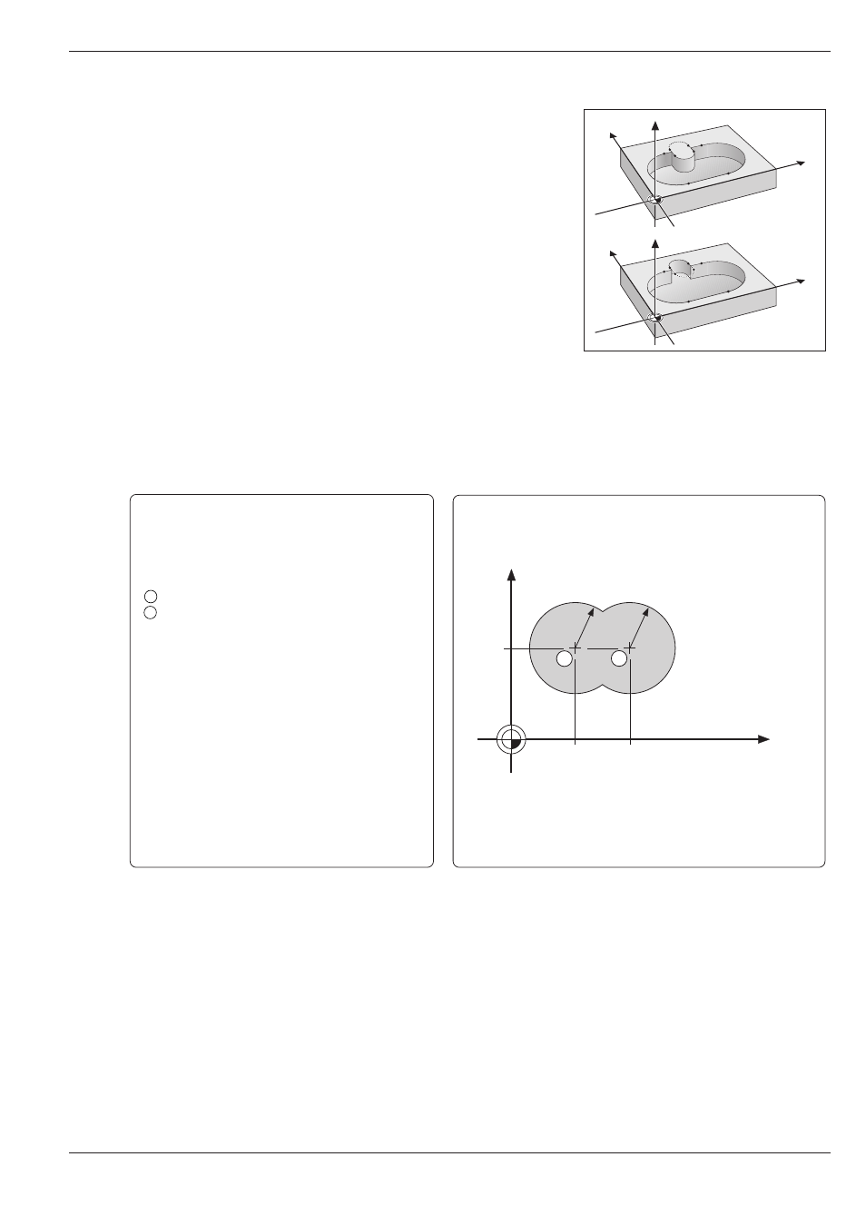
Fig. 8.16:
Examples of overlapping contours
8.3
SL Cycles
Y
X
Z
Y
X
Z
Y
35
65
50
X
R25
R25
1
2
Continued...
Overlapping contours
Pockets and islands can be overlapped to form a new contour. The area of
a pocket can thus be enlarged by another pocket or reduced by an island.
Starting position
Machining begins at the starting position of the first pocket in cycle G37
CONTOUR GEOMETRY. The starting position should be located as far as
possible from the overlapping contours.
Example: Overlapping pockets
Machining begins with the first contour label defined in block 6. The first
pocket must begin outside the second pocket.
Inside machining with a center-cut end mill
(ISO 1641), tool radius 3 mm.
Coordinates of the circle centers:
1
X = 35 mm
Y
=
50 mm
2
X = 65 mm
Y
=
50 mm
Circle radii
R = 25 mm
Setup clearance:
2 mm
Milling depth:
10 mm
Pecking depth:
5 mm
Feed rate for pecking:
500 mm/min
Finishing allowance:
0
Rough-out angle:
0
Milling feed rate:
500 mm/min