Bolt hole circles -15 – HEIDENHAIN TNC 360 ISO Programming User Manual
Page 149

7-15
TNC 360
7
Programming with Q Parameters
7.8
Examples for Exercise
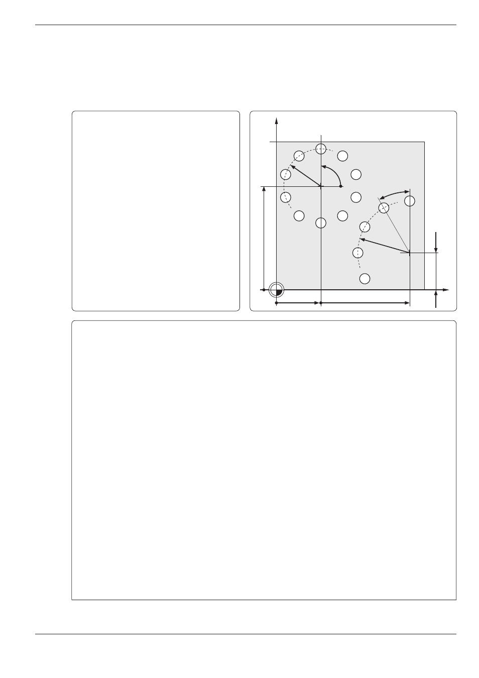
Bolt hole circles
Bore pattern 1 distributed over a full circle:
Entry values are listed below in program blocks
N10 to N80.
Movements in the plane are programmed
with polar coordinates.
Bore pattern 2 distributed over a circle sector:
Entry values are listed below in blocks N150 to
N190; Q5, Q7 and Q8 remain the same.
The holes are executed with cycle G83:
PECKING (see page 8-4)
X
Y
30
90
1
2
25
35
25
70
90°
30°
Part program
%3600715 G71 * ....................................................... Load data for bolt hole circle 1
N10 D00 Q01 P01 +30 * ............................................ Circle center X coordinate
N20 D00 Q02 P01 +70 * ............................................ Circle center Y coordinate
N30 D00 Q03 P01 +11 * ............................................ Number of holes
N40 D00 Q04 P01 +25 * ............................................ Circle radius
N50 D00 Q05 P01 +90 * ............................................ Starting angle
N60 D00 Q06 P01 +0 * .............................................. Hole angle increment (0: distribute holes over 360°)
N70 D00 Q07 P01 +2 * .............................................. Setup clearance
N80 D00 Q08 P01 +15 * ............................................ Total hole depth
N90 G30 G17 X+0 Y+0 Z-20 *
N100 G31 G90 X+100 Y+100 Z+0 *
N110 G99 T1 L+0 R+4 *
N120 T1 G17 S2500 *
N130 G83 P01 -Q07 ................................................... Definition of the pecking cycle/setup clearance
P02 -Q08 .......................................................... Total hole depth according to the load data
P03 -5 .............................................................. Pecking depth
P04 0 ............................................................... Dwell time
P05 250 * ........................................................ Feed rate for pecking
N140 L1,0 * ................................................................ Call bolt hole circle 1
Load data for bolt hole circle 2 (only re-enter changed data)
N150 D00 Q1 P01 +90 * ............................................ New circle center X coordinate
N160 D00 Q2 P01 +25 * ............................................ New circle center Y coordinate
N170 D00 Q3 P01 +5 * .............................................. New number of holes
N180 D00 Q4 P01 +35 * ............................................ New circle radius
N190 D00 Q6 P01 +30 * ............................................ New hole angle increment (not a full circle, 5 holes at 30°
intervals)
N200 L1,0 * ................................................................ Call bolt hole circle 2
N210 G00 G40 G90 Z+200 M02 * ............................. End of main program
Continued...