Tapping with floating tap holder g84 -6 – HEIDENHAIN TNC 360 ISO Programming User Manual
Page 159
8-6
8
Cycles
TNC 360
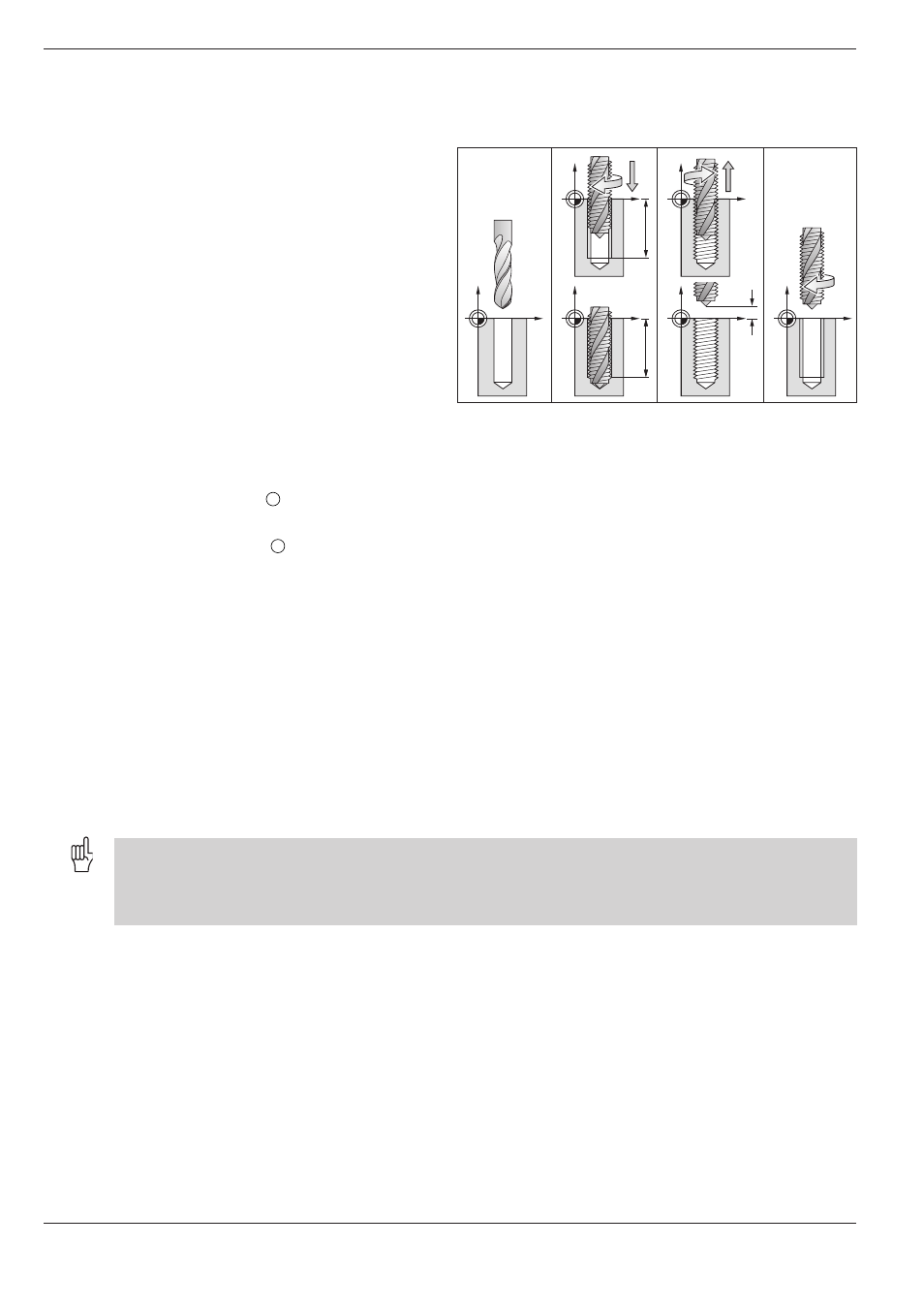
Fig. 8.2: TAPPING cycle
8.2
Simple Fixed Cycles
1.
2.
3.
4.
B
B
A
B
TAPPING with floating tap holder G84
Process
• The thread is cut in one pass.
• When the tool reaches the total hole depth, the
direction of spindle rotation is reversed. After the
programmed dwell time the tool is retracted to
the starting position.
• At the starting position, the direction of rotation
is reversed once again.
Required tool
A floating tap holder is required for tapping. The
floating tap holder compensates the tolerances for
feed rate and spindle speed during the tapping
process.
Input data
• SETUP CLEARANCE
A
:
Distance between tool tip (starting position) and workpiece surface.
Standard value: 4x thread pitch.
• TOTAL HOLE DEPTH
B
(thread length):
Distance between workpiece surface and end of thread.
• DWELL TIME:
Enter a dwell time between 0 and 0.5 seconds to prevent wedging of
the tool when retracted. (Further information is available from the
machine tool builder.)
• FEED RATE F:
Traversing speed of the tool during tapping.
Calculations
The feed rate is calculated as follows:
F = S x p
F: Feed rate (mm/min)
S: Spindle speed (rpm)
p: Thread pitch (mm)
• When a cycle is being run, the spindle speed override control is disabled. The feed rate override control is only
active within a limited range (preset by the machine tool builder).
• For tapping right-hand threads activate the spindle with M3; for left-hand threads use M4.