Yx z, Absolute workpiece positions, Incremental workpiece positions – HEIDENHAIN TNC 360 ISO Programming User Manual
Page 28
TNC 360
1-11
1
Introduction
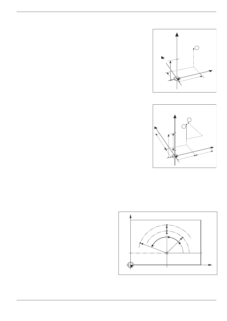
Fig. 1.16:
Position ➀ of the example
"absolute workpiece positions"
Fig. 1.17:
Positions ➁ and ➂ of the example
"incremental workpiece positions"
Y
X
Z
1
20
10
Z=15mm
X=20mm
Y=10mm
15
I
Z=–15mm
Y
X
Z
2
10
5
5
15
20
10
10
I
X=10mm
I
Y=10mm
3
0
0
Fig. 1.18:
Incremental dimensions in polar coordinates (designated
with "G91")
1.2
Fundamentals of NC
X
Y
J = 10
0
°
I = 30
R
R
R
G91R
G91H
G91H
H
Absolute workpiece positions
Each position on the workpiece is clearly defined by its absolute coordi-
nates.
Example: Absolute coordinates of the position ➀:
X = 20 mm
Y = 10 mm
Z = 15 mm
If you are drilling or milling a workpiece according to a workpiece drawing
with absolute coordinates, you are moving the tool to the coordinates.
Incremental workpiece positions
A position can be referenced to the previous nominal position: i.e. the
relative datum is always the last programmed position. Such coordinates
are referred to as incremental coordinates (increment = growth), or also
incremental or chain dimensions (since the positions are defined as a
chain of dimensions). Incremental coordinates are designated with G91.
Example: Incremental coordinates of the position ➂
referenced to position ➁
Absolute coordinates of the position ➁ :
X = 10 mm
Y = 5 mm
Z = 20 mm
Incremental coordinates of the position ➂ :
IX = 10 mm
IY = 10 mm
IZ = –15 mm
If you are drilling or milling a workpiece according to a workpiece drawing
with incremental coordinates, you are moving the tool by the coordinates.
An incremental position definition is therefore intended as an immediately
relative definition. This is also the case when a position is defined by the
distance-to-go to the target position (here the relative datum is located at
the target position). The distance-to-go has a negative algebraic sign if the
target position lies in the negative axis direction from the actual position.
The polar coordinate system can also express both
types of dimensions:
• Absolute polar coordinates always refer to the
pole I, J and the angle reference axis.
• Incremental polar coordinates always refer to
the last programmed nominal position of the
tool.