Yx z – HEIDENHAIN TNC 360 ISO Programming User Manual
Page 127
6
Subprograms and Program Section Repeats
TNC 360
6-4
60
15
45
75
10
3
1
2
20
20
20
5
Y
X
Z
6.1
Subprograms
Part program
%S64I G71 * .................................................................. Begin program
N10 G30 G17 X+0 Y+0 Z–20 * ...................................... Define the workpiece blank
N20 G31 G90 X+100 Y+100 Z+0 *
N30 G99 T1 L+0 R+2.5 * ............................................... Define the tool
N40 T1 G17 S3500 * ...................................................... Call the tool
N50 G83 P01 –2 P02 –10 P03 –5 P04 0
P05 100 * ....................................................................... Cycle definition PECKING (see page 8-5)
N60 G00 G40 G90 Z+100 M06 * ................................... Retract the spindle and insert the tool
N70 X+15 Y+10 * .......................................................... Move to hole group 1
N80 Z+2 M03 * .............................................................. Pre-position in the infeed axis
N90 L1,0 * ..................................................................... Subprogram call (with block N90 the subprogram is
.......................................................................................
executed)
N100 X+45 Y+60 * ........................................................ Move to hole group 2
N110 L1,0 * ................................................................... Subprogram call
N120 X+75 Y+10 * ........................................................ Move to hole group 3
N130 L1,0 * ................................................................... Subprogram call
N140 Z+100 M02 * ........................................................ Retract tool;
.......................................................................................
End of main program (M2); the subprogram is
.......................................................................................
entered after M2
N150 G98 L1 * ............................................................... Beginning of subprogram
N160 G79 * .................................................................... Execute pecking for the first hole
N170 G91 X+20 M99 * .................................................. Move to incremental position for second hole and drill
N180 Y+20 M99 * ......................................................... Move to incremental position for third hole and drill
N190 X–20 G90 M99 * .................................................. Move to incremental position for fourth hole and drill;
.......................................................................................
Switch to absolute coordinates (G90)
N200 G98 L0 * ............................................................... End of subprogram
N9999 %S64I G71 * ...................................................... End of program
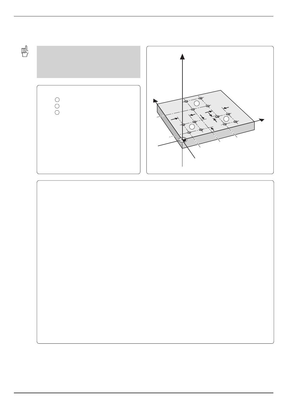
Example for exercise: Group of four holes at three different locations
The holes are drilled with cycle G83 PECKING.
You enter the total hole depth, setup clearance,
drilling feed rate, etc. once in the cycle. You can
then call the cycle with the miscellaneous func-
tion M99 (see page 8-3).
Coordinates to the first hole in each group:
Group
1
X = 15 mm
Y = 10 mm
Group
2
X = 45 mm
Y = 60 mm
Group
3
X = 75 mm
Y = 10 mm
Spacing of holes:
X
=
20 mm
Y
=
20 mm
Total hole depth (DEPTH):
Z
=
10 mm
Hole diameter:Ø
=
5 mm