HEIDENHAIN TNC 360 ISO Programming User Manual
Page 138
TNC 360
7-4
7
Programming with Q Parameters
7.1
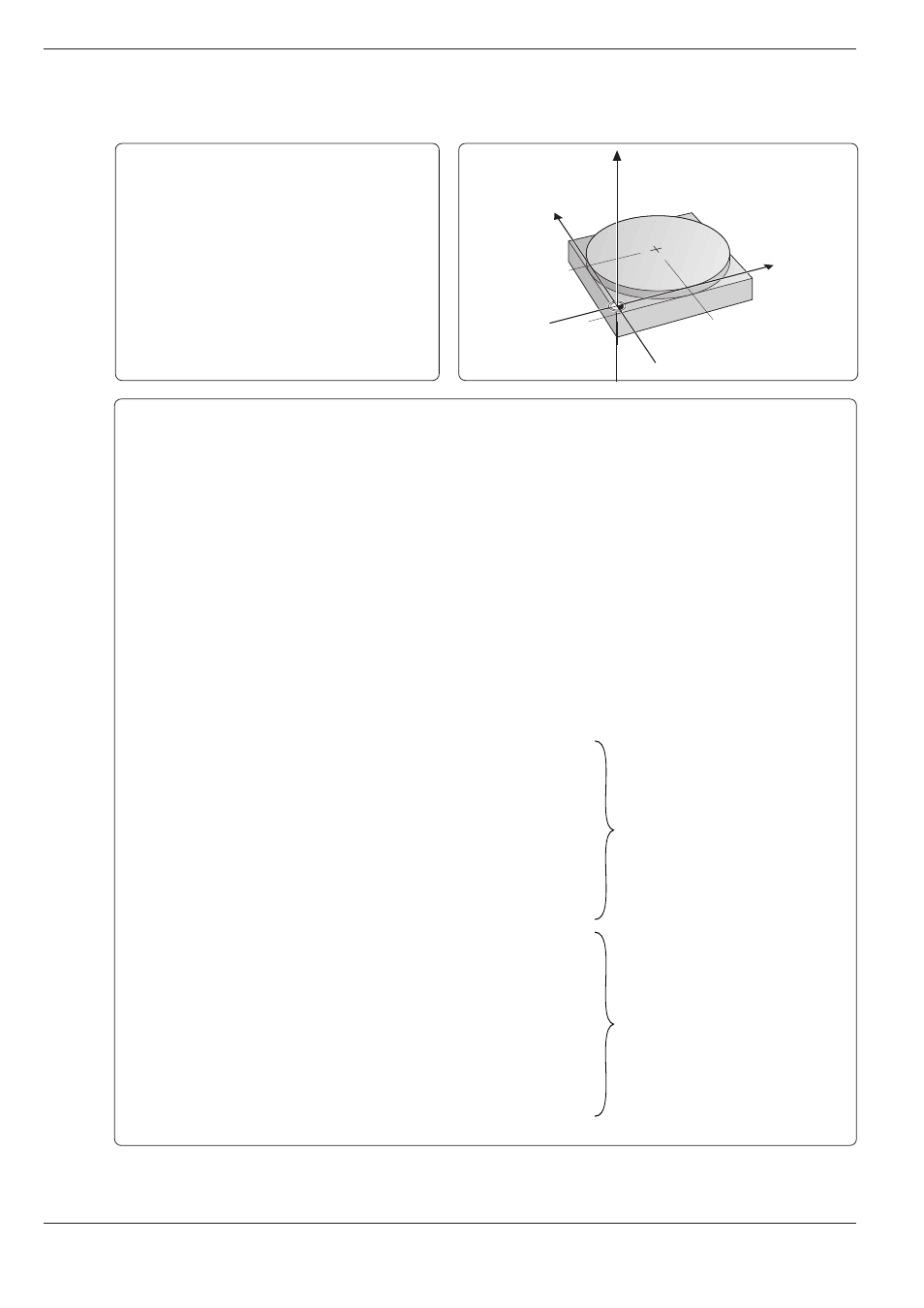
Q Parameters Instead of Numerical Values
Example for exercise: Full circle
Circle center I,J:
X
= 50 mm
Y
= 50 mm
Beginning and end of the circular arc:
X
= 50 mm
Y
=
0 mm
Milling depth:
ZM = –5 mm
Tool radius:
R
= 15 mm
Blocks N130 to N240:
Corresponding to blocks N10 to
N120 from program S520I
Blocks N10 to N120:
Assign numerical values to the
Q parameters
Part program without Q parameters
%S520I G71 * ............................................................ Start of program
N10 G30 G17 X+1 Y+1 Z-20 * ................................... Definition of blank form MIN point
N20 G30 G90 X+100 Y+100 Z+0 * ............................ Definition of blank form MAX point
N30 G99 T6 L+0 R+15 * ............................................ Tool definition
N40 T6 G17 S500 * .................................................... Tool call
N50 I+50 J+50 * ........................................................ Coordinates of the circle center
N60 G00 G40 G90 Z+100 M06 * ............................... Retract the spindle and insert the tool
N70 X+30 Y–20 * ....................................................... Pre-position the tool
N80 Z–5 M03 * .......................................................... Pre-position the tool to working depth
N90 G01 G41 X+50 Y+0 F100 * ................................ Move to first contour point with radius compensation
N100 G02 X+50 Y+0 * ............................................... Mill circular arc around circle center I,J; coordinates of end
point X = +50 and Y = 0; positive direction of rotation (G02)
N110 G00 G40 X+70 Y–20 * ...................................... Retract the tool in X, Y; cancel radius compensation
N120 Z+100 M02 * .................................................... Retract the tool in Z
N9999 %S520I G71 *
Part program with Q parameters
%3600741 G71 *
N10 D00 Q01 P01 +100 * .......................................... Clearance height
N20 D00 Q02 P01 +30 * ............................................ Start pos. X
N30 D00 Q03 P01 –20 * ............................................ Start-End pos. Y
N40 D00 Q04 P01 +70 * ............................................ End pos. X
N50 D00 Q05 P01 –5 * .............................................. Milling depth
N60 D00 Q06 P01+50 * ............................................. Circle center X
N70 D00 Q07 P01 +50 * ............................................ Circle center Y
N80 D00 Q08 P01 +50 * ............................................ Circle start point X
N90 D00 Q09 P01 +0 * .............................................. Circle start point Y
N100 D00 Q10 P01 +0 * ............................................ Tool length L
N110 D00 Q11 P01 +15 * .......................................... Tool radius R
N120 D00 Q20 P01 +100 * ........................................ Milling feed rate F
N130 G30 G17 X+0 Y+0 Z–20 *
N140 G31 G90 X+100 Y+100 Z+0 *
N150 G99 T1 L+Q10 R+Q11 *
N160 T1 G17 S500 *
N170 I+Q6 J+Q7 *
N180 G00 G40 G90 Z+Q1 M06 *
N190 X+Q2 Y+Q3 *
N200 Z+Q5 M03 *
N210 G01 G41 X+Q8 Y+Q9 FQ20 *
N220 G02 X+Q8 Y+Q9 *
N230 G01 G40 X+Q4 Y+Q3 *
N240 Z+Q1 M02 *
N9999 %3600741 G71 *
–5
50
50
Y
X
Z
I, J