3d touch probe system -9, 3d touch probe applications -9, 4 3d touch probe system – HEIDENHAIN TNC 360 ISO Programming User Manual
Page 46
TNC 360
2-9
2
Manual Operation and Setup
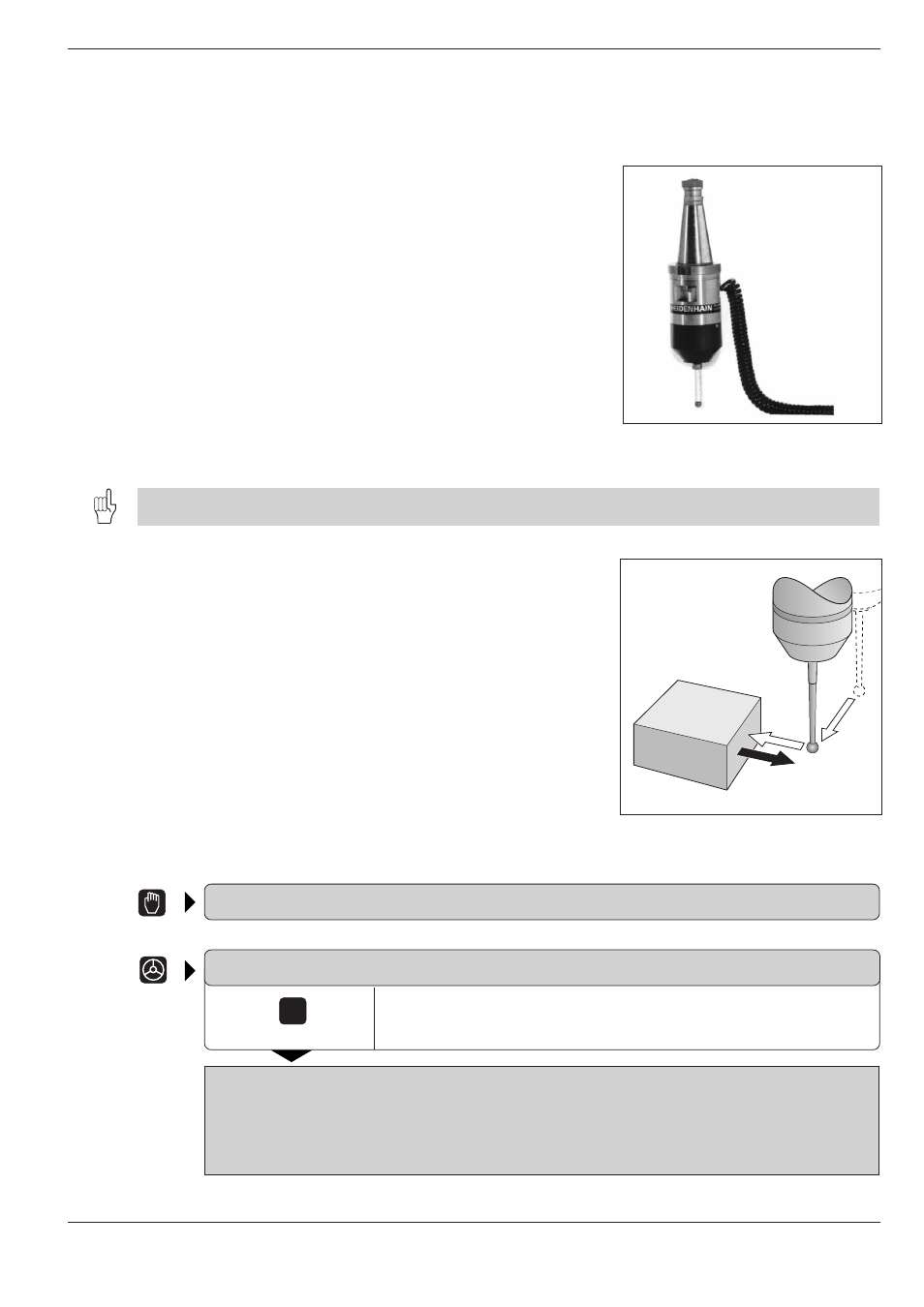
Fig. 2.7:
HEIDENHAIN TS 120 three-
dimensional touch probe system
Fig. 2.8:
Feed rates during probing
TOUCH
PROBE
F
max
F
F
2.4 3D Touch Probe System
3D Touch probe applications
The TNC provides touch functions for application of a HEIDENHAIN 3D
touch probe. Typical applications for the touch probe system are:
• Compensating workpiece misalignment
(basic rotation)
• Datum setting
• Measuring:
- Lengths and positions on the workpiece
- Angles
- Circle radii
- Circle centers
• Measurements under program control
• Digitizing 3D surfaces (optional, only available with HEIDENHAIN plain
language dialog programming.)
The TNC must be specially prepared by the machine tool builder for the use of a 3D touch probe.
After you press the machine START button, the touch probe begins
executing the selected probe function. The machine tool builder sets the
feed rate F at which the probe approaches the workpiece. When the 3D
touch probe contacts the workpiece, it
• transmits a signal to the TNC, which stores the coordinates of the
probed position
• stops moving
• returns to its starting position in rapid traverse
Selecting the touch probe menu
MANUAL OPERATION
or
ELECTRONIC HANDWHEEL
Select the menu of touch probe functions.
CALIBRATION EFFECTIVE LENGTH
CALIBRATION EFFECTIVE RADIUS
BASIC ROTATION
SURFACE = DATUM
CORNER = DATUM
CIRCLE CENTER = DATUM