Slot milling g74 -9, Slot milling g74 – HEIDENHAIN TNC 360 ISO Programming User Manual
Page 162
8-9
8
Cycles
TNC 360
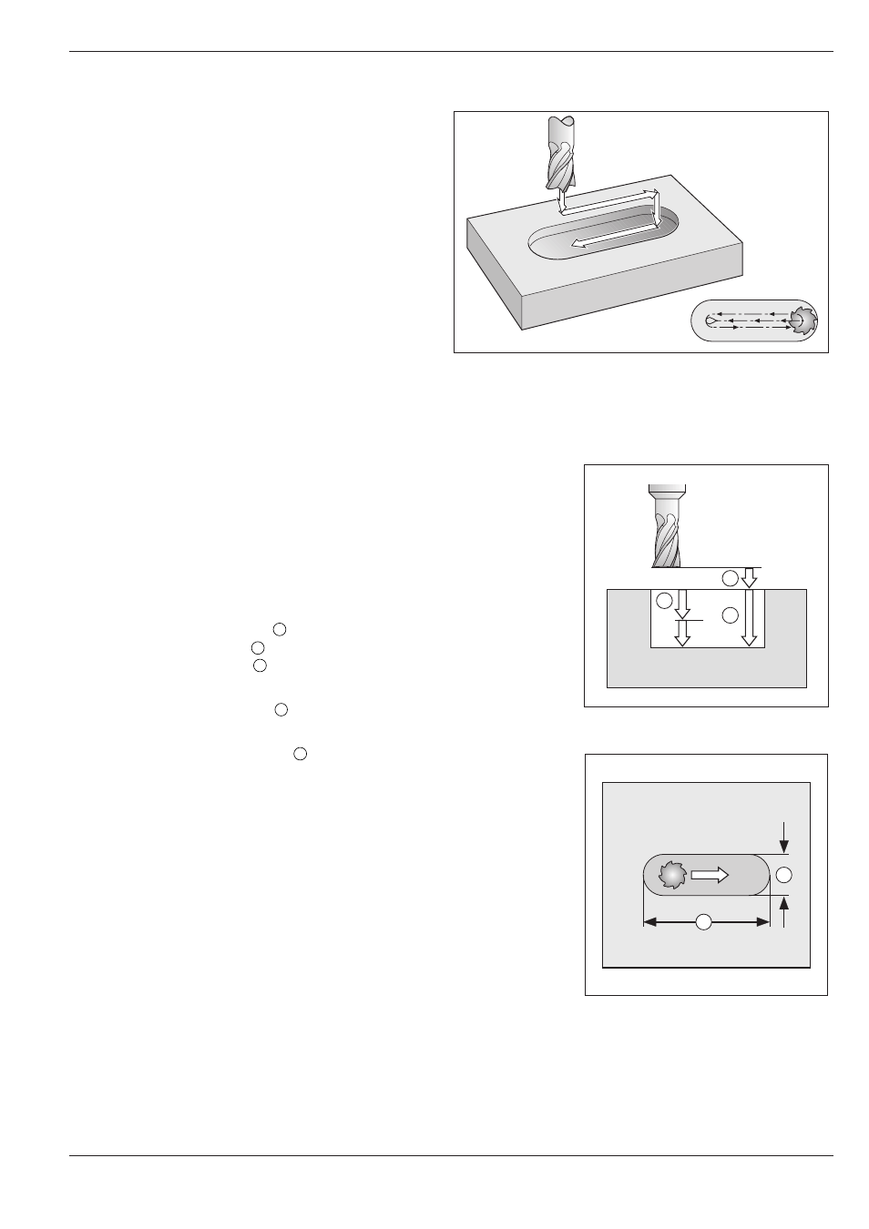
Fig. 8.4:
SLOT MILLING cycle
Fig. 8.6:
Side lengths of the slot
8.2
Simple Fixed Cycles
Fig. 8.5:
Infeeds and distances for the
SLOT MILLING cycle
A
B
C
E
D
SLOT MILLING G74
Process
Roughing process:
• The tool penetrates the workpiece from the
starting position and mills in the longitudinal
direction of the slot.
• After downfeed at the end of the slot, milling is
performed in the opposite direction.
These steps are repeated until the programmed
milling depth is reached.
Finishing process:
• The control advances the tool in a quarter circle
at the bottom of the slot by the remaining
finishing cut. The tool subsequently climb mills
the contour (with M3).
• At the end of the cycle, the tool is retracted in
rapid traverse to the setup clearance.
If the number of infeeds was odd, the tool
returns to the starting position at the level of the
setup clearance.
Required tool
This cycle requires a center-cut end mill (ISO 1641). The cutter diameter
must not be larger than the width of the slot and not smaller than half the
width of the slot. The slot must be parallel to an axis of the current
coordinate system.
Input data
• SETUP CLEARANCE
A
• MILLING DEPTH
B
: Depth of the slot
• PECKING DEPTH
C
• FEED RATE FOR PECKING:
Traversing speed of the tool during penetration.
• FIRST SIDE LENGTH
D
:
Length of the slot. Specify the sign to determine the first milling
direction.
• SECOND SIDE LENGTH
E
:
Width of the slot
• FEED RATE:
Traversing speed of the tool in the working plane.