Projection in three planes -16 3d view -16, Projection in three planes, 3d view – HEIDENHAIN TNC 360 ISO Programming User Manual
Page 33
TNC 360
1-16
1
Introduction
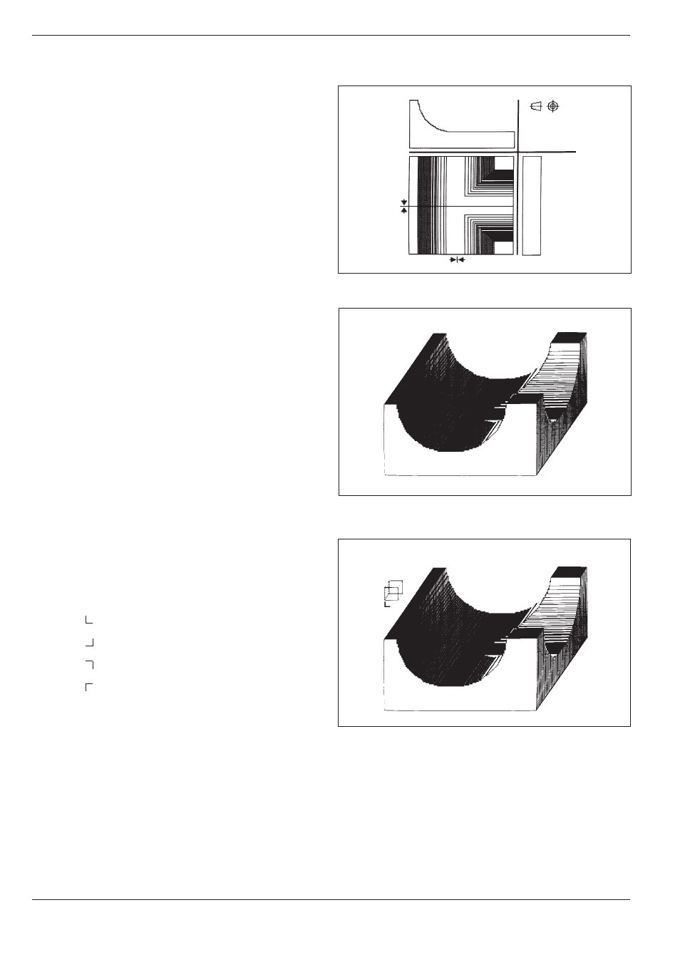
Fig. 1.24:
TNC graphics, projection in three planes
Fig. 1.25:
TNC graphics, 3D view
Fig. 1.26:
Rotated 3D view
1.4
Graphics and Status Display
Projection in three planes
Here the program is displayed as in a technical
drawing, with a plan view and two orthographic
sections. A conical symbol near the graphic indi-
cates whether the display is in first angle or second
angle projection according to ISO 6433, Part 1. The
type of projection can be selected with MP 7310.
Moving the sectional planes
The sectional planes can be moved to any position
with the arrow keys. The position of the sectional
plane is displayed on the screen while it is being
moved.
3D view
This mode displays the simulated workpiece in
three-dimensional space.
Rotating the 3D view
In the 3D view, the image can be rotated around
the vertical axis with the horizontal arrow keys.
The angle of orientation is indicated with a special
symbol:
0
0
rotation
90
0
rotation
180
0
rotation
270
0
rotation
3D view, not true to scale
If the height-to-side ratio is between 0.5 and 50, a non-scaled 3D view can
be selected with the vertical arrow keys. This view improves the resolu-
tion of the shorter workpiece side.
The angle orientation symbol also indicates the angle of orientation of the
non-scaled 3D view.