Graphics and status display -15, Plan view -15, 4 graphics and status display – HEIDENHAIN TNC 360 ISO Programming User Manual
Page 32: Plan view
TNC 360
1-15
1
Introduction
1.4 Graphics and Status Display
The TNC features various graphic display modes for testing programs. To
be able to use this feature, you must select a program run operating
mode.
Workpiece machining is simulated graphically in the display modes:
• Plan view
• Projection in three planes
• 3D view
With the fast internal image generation, the TNC calculates the contour
and displays a graphic only of the completed part.
Select display mode
Select display mode menu.
Select desired display mode.
Confirm selection.
Start graphic display
Start graphic simulation in the selected display mode.
The START key repeats a graphic simulation as often as desired.
Rotary axis movements cannot be graphically simulated.
An attempted test run will result in an error message.
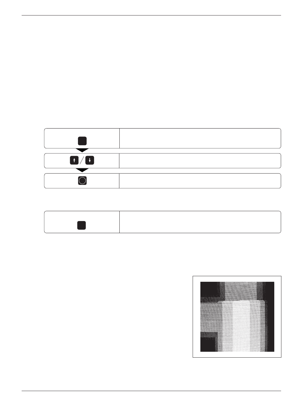
Plan view
In this mode, contour height is shown by image brightness.
The deeper the contour, the darker the image.
Number of depth levels: 7
This is the fastest of the three display modes.
GRAPHICS
ENT
START
GRAPHICS
MOD
2 x
Fig. 1.23:
TNC graphics, plan view