Calibrating the 3d touch probe -10 – HEIDENHAIN TNC 360 ISO Programming User Manual
Page 49
TNC 360
2-12
2
Manual Operation and Setup
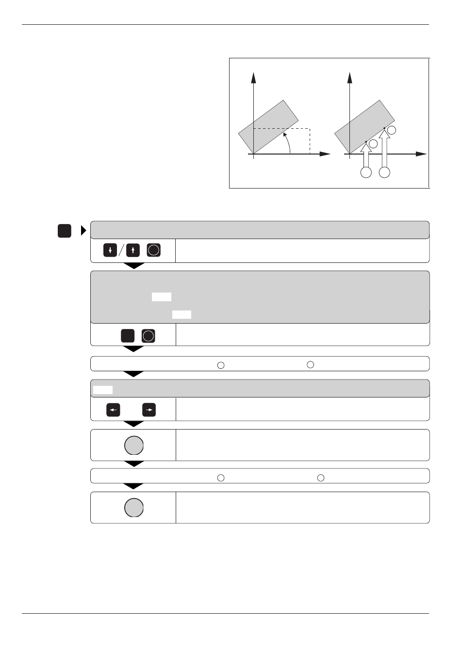
Fig. 2.11:
Basic rotation of a workpiece, probing procedure for com-
pensation (right). The dashed line is the nominal position;
the angle PA is being compensated.
or
2.4
3D Touch Probe System
PA
A
B
2
1
ENT
TOUCH
PROBE
0
e.g.
ENT
I
I
Compensating workpiece misalignment
The TNC electronically compensates workpiece
misalignment by computing a “basic rotation.”
Set the ROTATION ANGLE to the angle at which a
workpiece surface should be oriented with respect
to the angle reference axis (see p. 1-9) of the
working plane.
SURFACE = DATUM
Select the BASIC ROTATION probe function.
BASIC ROTATION
X+ X- Y+ Y–
ROTATION ANGLE =
Enter the nominal value of the ROTATION ANGLE.
Move the ball tip to a starting position
A
near the first touch point
1
.
X + X – Y + Y –
Select the probing direction.
Probe the workpiece.
Move the ball tip to a starting position
B
near the second touch point
2
.
Probe the workpiece.
A basic rotation is kept in non-volatile storage and is effective for all
subsequent program runs and graphic simulations.