Characteristics of the meter interface – Solare Datensysteme Solar-Log User Manual
Page 32
32
Optional Connections
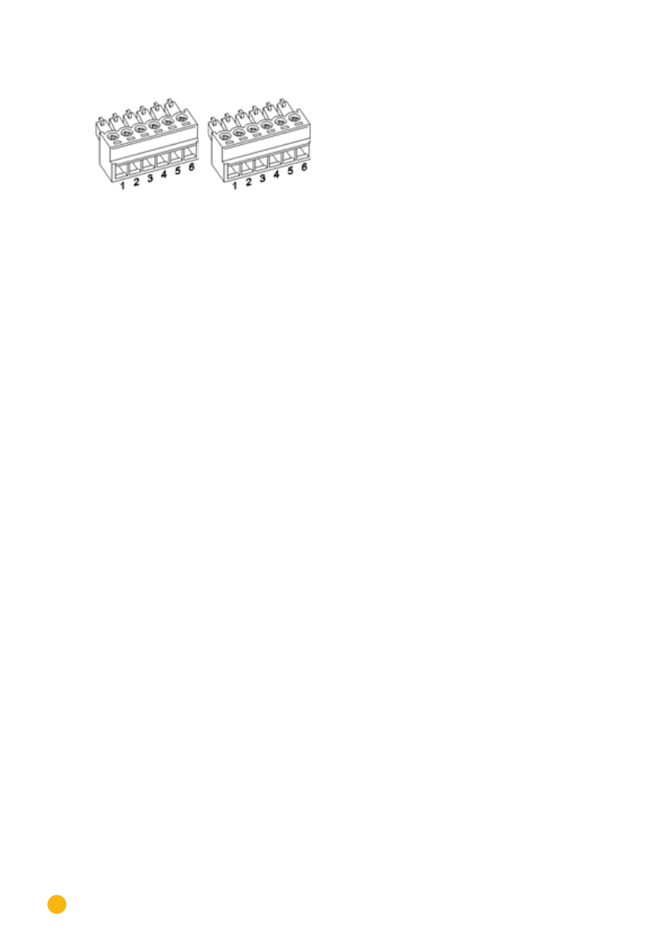
The current transformers have to be connected to the Meter interface with the secondary side.
Fig.: Two 6-pin terminal block connectors for the Meter interface
Solar-Log™ Meter 1
Interface
PIN
Description
Label
Current transformer
Meter 1
1
Current transformer/CT 1a
S1/k
2
Current transformer/CT 1b
S2/i
3
Current transformer/CT 2a
S1/k
4
Current transformer/CT 2b
S2/i
5
Current transformer/CT 3a
S1/k
6
Current transformer/CT 3b
S2/i
Solar-Log™ Meter 2
Interface
PIN
Description
Label
Current transformer
Meter 2
1
Current transformer/CT 1a
S1/k
2
Current transformer/CT 1b
S2/i
3
Current transformer/CT 2a
S1/k
4
Current transformer/CT 2b
S2/i
5
Current transformer/CT 3a
S1/k
6
Current transformer/CT 3b
S2/i
Characteristics of the Meter interface
The current transformer may not exceed a maximum output or secondary current of 200 mA. The input /
rated current is calculated by the maximum amount of power that is to be measured and has to be se-
lected for each measuring point. The current transformer's rated measuring ratio can be defined for each
current transformer input.
The current transformers have to be set up in a way so that only one current-carrying conductor is mea-
sured. Cables with multiple wires cannot be measured.
The maximum cable length between the current transformers and Solar-Log™ depends on the cable dia-
gram and the load of the current transformer.
We recommend a maximum cable length of 30 meters with a diameter of 0.75 mm
2
for our products.
For other current transformers, please consult the manufacturer's specifications in regard to cable length
and the wiring diagram.