5 digital outputs sub-d 9, 8 channels, 6 digital inputs m8 and m12, 7 digital inputs and outputs sub-d 25 – BECKHOFF EP2xxx User Manual
Page 98: Input connections, 25 pin sub‐d socket ﴾pins 1 ‐ 8, 25 pin sub‐d socket ﴾pins 9 ‐ 18, 5 digital outputs subd 9, 8 channels, 7 digital inputs and outputs subd 25
Mounting and cabling
3.6.5
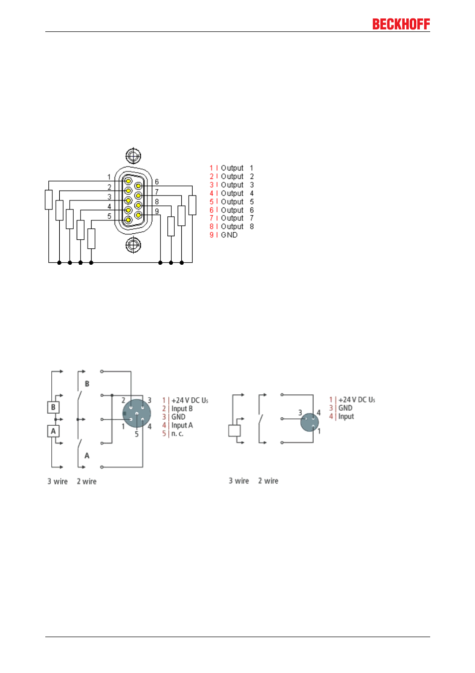
Digital outputs SubD 9, 8 channels
The IE2808 digital output module transmits the binary control signals from the automation unit on to the
actuators at the process level.
The 16 outputs deliver load currents of up to 0.5 A, although the total current from all the outputs must not
exceed 4 A.
The signal connection is made through two 9pin subD sockets
The outputs are shortcircuit proof and protected against inverse connection.
Fig. 93: Digital outputs SubD 9, 8 channels
3.6.6
Digital inputs M8 and M12
The digital input modules acquire the binary control signals from the process level and transmit them to the
higherlevel automation unit.
The signals are optionally connected via screwin M8 connectors (EP1xxx0001) or screwin M12 connectors
(EP1xxx0002).
Fig. 94: Digital inputs M8 and M12
The sensors are supplied from the control voltage Us with a maximum current of 0.5 A.
The state of the signals is indicated by light emitting diodes.
3.6.7
Digital inputs and outputs SubD 25
The EP2316008 digital combination module
• connects the binary control signals from the automation unit on to the actuators at the process level.
• acquires the binary control signals from the process level and transmits them to the higherlevel
automation unit.
EP2xxx
98
Version 2.1.0