Port configuration, Input/output ports (physical; navcom products), Input/output ports (logical) – NavCom LAND-PAK Rev.N User Manual
Page 21: Block diagram
Technical Reference Manual Rev. N
Blk = All;
Blu = IOP w/Internal Radio
;
Red = IOP & LBM
;
Grn = Engine only
19
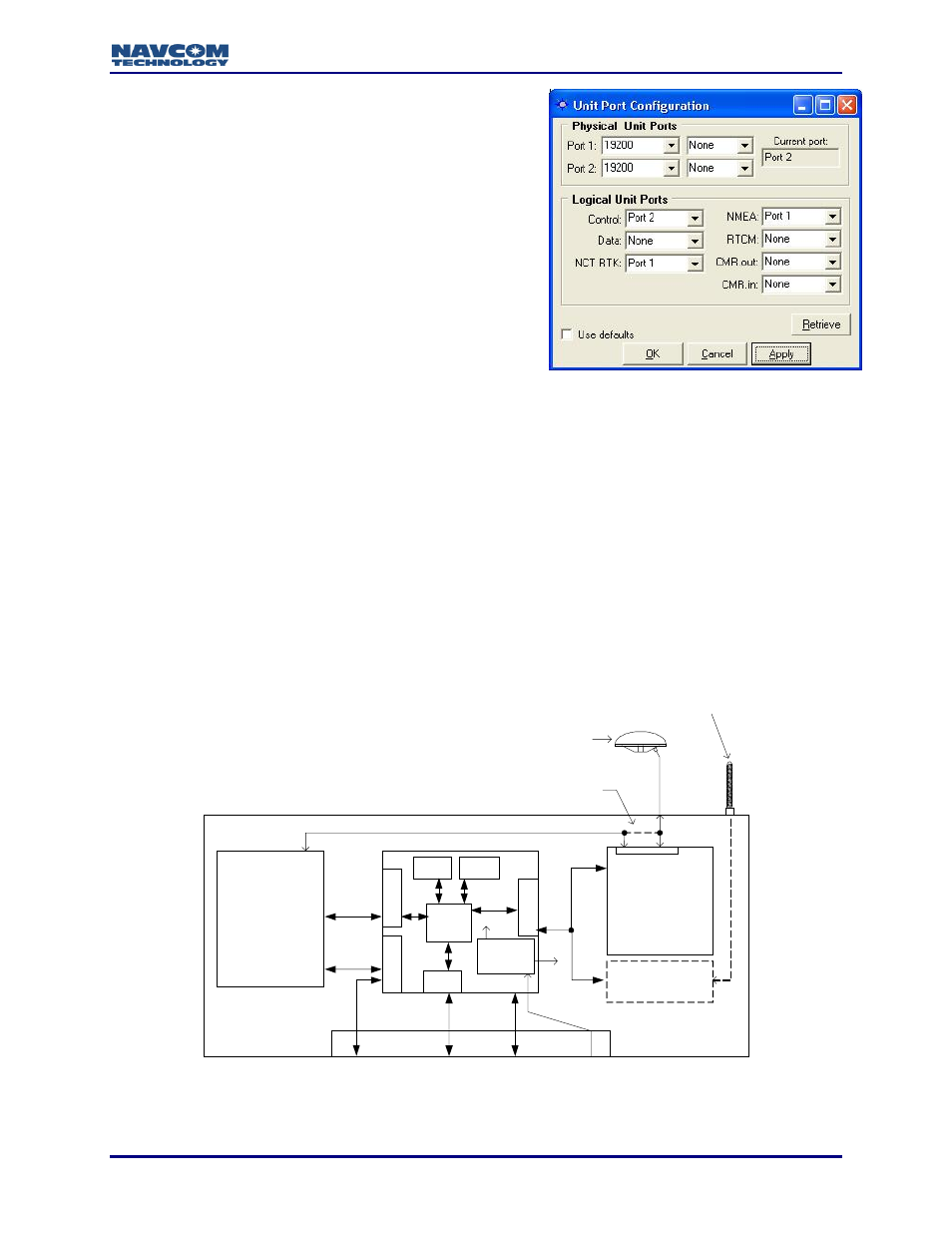
Port Configuration
Input/Output Ports (Physical; NavCom products):
PORTA = Serial Port #1 = COM 1
PORTB = Serial Port #2 = COM 2
Radio = Internal Radio Modem, RT- models only
(Optionally, may also contain a radio and/ or
CAN Bus)
Input/Output Ports (Logical):
Data is steered to a physical port based on it’s logical
assignment. This provides maximum flexibility of the
receivers interface. The illustration depicts a typical port
assignment. The x1a control string assigns each port’s usage:
Control (default, COM2)
RTCM
NCT-RTK / Diagnostic
CMR_in
Data (default, COM1)
CMR_out
NMEA (default, COM1)
Block Diagram
The typical receiver has three user configurable physical communications ports (two external
and one internal) and several logical communications ports. To aid in distinguishing these ports,
please refer to the block diagram below.
The data logging memory (MMC) is located on the IOP board. Recording data to the internal
memory is limited to a 1Hz rate as the communication between the GPS engine and the IOP is
19.2k baud. When downloading the MMC memory, connect to Com1 for the fastest available
download rate. A full memory will take about 3.5 hours to download at 115kbps.
GPS Engine
NCT-2000D
NCT-2100D
IOP
StarFire™
LBM
SF Models
Except
SF-2050R
RTK Radio
RT Models
19.2K
19.2K
When LBM is not present
Com2
Com1
1PPS
Event
CAN
115K
115K
07-00037-C
GPS / StarFire Antenna
RTK Antenna
5VDC
50mA
115K
MMC
Voltage
Regulator
µP
Flash
UART
10 to 30
VDC
U
A
R
T
U
A
R
T
U
A
R
T