Communication port connectivity – NavCom LAND-PAK Rev.N User Manual
Page 22
Technical Reference Manual Rev. N
Blk = All;
Blu = IOP w/Internal Radio
;
Red = IOP & LBM
;
Grn = Engine only
20
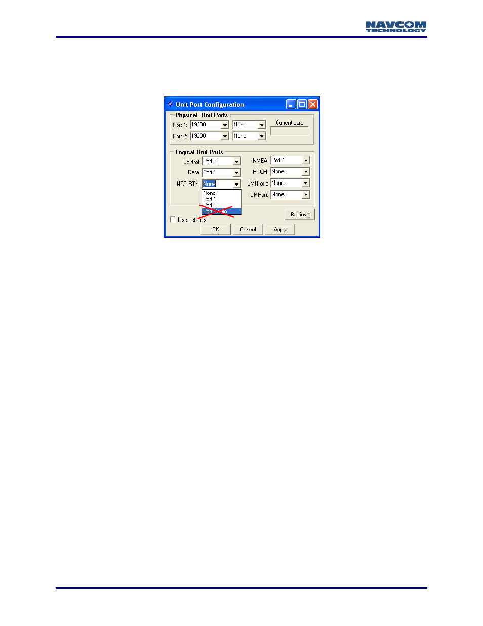
These user configurable physical ports are Com1, Com2, and Radio/Diagnostic.
The Com ports are described in the next section. The Radio/Diagnostic port
connects to an internal UHF radio in NavCom’s RT-line of products and is not used,
nor should it be assigned as a logical port in any of the SF-line products.
Communication Port Connectivity
Connect the supplied LEMO 7-Pin connector of the serial cable (P/N 94-310059-3006) to COM
2 (factory default Control Port) of the receiver. Connect the DB9 end to the control device.
The receiver is configured as a DCE device.
COM 2 is the logical control port by default. COM 1 can be configured as the control port.
However, there are caveats to Logical / Physical port assignments.
The Control Port is a logical input/output port and can not share the physical port with
any other logical port. The Control Port typically handles the most data and requires
baud rates in excess of 19.2K baud, particularly in multi-hertz measurement and
navigation applications. Though Com 1 is physically capable of operating at 115K baud,
the throughput from the NCT-2100D to the IOP is limited to 19.2K baud. Thus, the
recommendation to maintain Com 2 as the Control port for multi-hertz applications.
In the Rover, the NMEA Port is an output logical port and may share the data physical
port with RTCM, CMR, or NCT RTK input corrections. In the Base Station, the NMEA
port can not share the data port with any RTCM, CMR, or NCT RTK output corrections.