Wiring fast ethernet ports – Westermo MRI-128-F4G-PSE24 User Manual
Page 12
8
2.6
Wiring Fast Ethernet Ports
The switch includes up to 24 RJ-45 Fast Ethernet ports. The Fast Ethernet ports
support 10Base-T and 100Base-TX, full or half duplex modes. All the Fast
Ethernet ports will auto-detect the signal from connected devices to negotiate
the link speed and duplex mode. Auto MDI/MDIX allows users to connect
another switch, hub or workstation without changing straight through or
crossover cables.
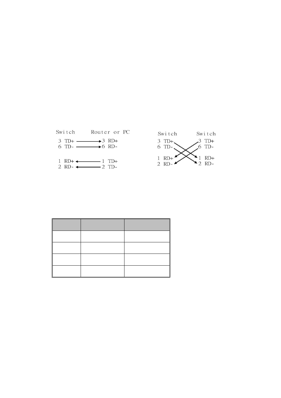
Note that crossover cables simply cross-connect the transmit lines at each end
to the received lines at the opposite end.
Straight-through Cabling Schematic
Cross-over Cabling Schematic
Note that Ethernet cables use pins 1, 2, 3, and 6 of an 8-pin RJ-45 connector. The
signals of these pins are converted by the automatic MDI-X function, as shown in
the table below:
Pin MDI-X Signals
MDI Signals
1
RD+
TD+
2
RD-
TD-
3
TD+
RD+
6
TD-
RD-
Connect one side of an Ethernet cable into any switch port and connect the
other side to your attached device. The LNK LED will light up when the cable is
correctly connected. Refer to the LED Indicators section for descriptions of each
LED indicator. Always make sure that the cables between the switches and
attached devices (e.g. switch, hub, or workstation) are less than 100 meters (328
feet).
The wiring cable types are as below.
10Base-T : 2-pair UTP/STP Cat. 3, 4, 5 cable, EIA/TIA-568 100-ohm (100m)
100Base-TX: 2-pair UTP/STP Cat. 5 cable, EIA/TIA-568 100-ohm (100m)