B1-02: run command selection for auto mode – Yaskawa Z1000U User Manual
Page 116
Drive
A1 Analog Input 1
0 to 10 V
AC Analog input common
2 k
+V 10.5 V, 20 mA power supply
A2 Analog Input 2
A3 Analog Input 3
Drive
A1 Analog Input 1
AC Analog input common
+V 10.5 V, 20 mA power supply
A2 Analog Input 2
A3 Analog Input 3
4 k
-10 to 10 V
OR
Customer
+/- 10 V
Supply
+10 V
-10 V
Common
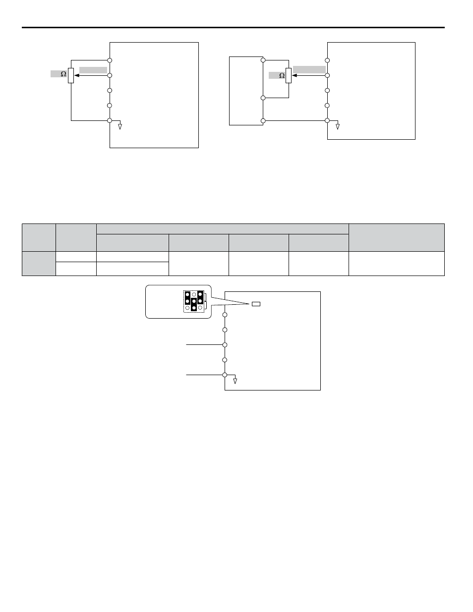
Figure 4.12 Setting the Frequency Reference as a Voltage Signal at Terminal A1
Current Input
Input terminals, A1, A2, and A3 can accept a current input signal. Refer to
for an example to set terminal A2 for
current input.
Table 4.16 Analog Input Settings for Frequency Reference Using a Current Signal
Terminal
Signal
Level
Parameter Settings
Notes
Signal Level
Selection
Function
Selection
Gain
Bias
A2
4 to 20 mA
H3-09 = 2
H3-10 = 0
(Frequency Bias)
H3-11
H3-12
Make sure to set jumper S1 on the
terminal board to “I” for current
input.
0 to 20 mA
H3-09 = 3
Drive
A1 Analog Input 1
0 or 4 to 20 mA
AC Analog input common
+V 10.5 V, 20 mA power supply
A2 Analog Input 2
A3 Analog Input 3
Jumper S1
A1/A2/A3
Voltage/Current
Selection
V
I
A1 A2 A3
Figure 4.13 Setting the Frequency Reference as a Current Signal to Terminal A2
Switching between Main/Auxiliary Frequency References
The frequency reference input can be switched between the analog terminals A1, A2, and A3 using multi-speed inputs.
to Multi-Step Speed Selection on page 157
for details on using this function.
Setting 2: Serial Communication (APOGEE FLN, BACnet, MEMOBUS/Modbus, Metasys N2)
This setting requires entering the frequency reference via the RS-422/RS-485 serial communications port (control terminals
R+, R-, S+, and S-).
Setting 3: Option card
This setting requires entering the frequency reference via an option board plugged into connector CN5-A on the drive control
board. Consult the option board manual for instructions on integrating the drive with the communication system.
Note:
If the frequency reference source is set for Option PCB (b1-01 = 3), but an option board is not installed, an oPE05 operation error will be
displayed on the digital operator and the drive will not run.
n
b1-02: Run Command Selection for AUTO Mode
Determines the Run command selection for AUTO mode.
4.7 Basic Drive Setup Adjustments
116
YASKAWA ELECTRIC TOEP C710636 10B Z1000U HVAC MATRIX Drive User Manual