Yaskawa Z1000U User Manual
Page 124
n
E5-09: Motor Induction Voltage Constant 1 (Ke) (for PM Motors)
Sets the induced peak voltage per phase in units of 0.1 mV/(rad/s) [electrical angle]. Set this parameter when using an IPM
motor with derated torque (SSR1 series or equivalent) or an IPM motor with constant torque (SST4 series or equivalent).
Set the voltage constant with E5-09 or E5-24 when E5-01 is set to FFFF. This parameter is set during Auto-Tuning for PM
motors.
No.
Parameter Name
Setting Range
Default
E5-09
Motor Induction Voltage Constant 1 (for PM Motors)
0.0 to 2000.0 mV/(rad/s)
Determined by
E5-01
Note:
Set E5-24 to 0 when setting E5-09. However, setting both E5-09 and E5-24 to 0 will trigger an alarm. An alarm will also be triggered if
neither E5-09 nor E5-24 are set to 0. When E5-01 is set to FFFF, then E5-09 = 0.0.
n
E5-24: Motor Induction Voltage Constant 2 (Ke) (for PM Motors)
Set the induced phase-to-phase rms voltage in units of 0.1 mV/(r/min) [mechanical angle]. Set this parameter when using an
SPM Motor (SMRA Series or equivalent).
When E5-01 is set to FFFF, use either E5-09 or E5-24 for setting the voltage constant. This parameter is set during Parameter
Auto-Tuning for PM motors.
No.
Parameter Name
Setting Range
Default
E5-24
Motor Induction Voltage Constant 2 (for PM Motors)
0.0 to 6500.0 mV/(r/min)
Determined by
E5-01
Note:
Set E5-24 to 0.0 when setting E5-09. However, setting both E5-09 and E5-24 to 0.0 will trigger an alarm. An alarm will also be triggered
if neither E5-09 nor E5-24 are set to 0.0. When E5-01 is set to FFFF, then E5-09 should be set to 0.0.
n
H2-06: Power Consumption Output Unit Selection
When one of the multi-function terminals is set to power consumption pulse output (H2-01, H2-02, or H2-03 = 39), parameter
H2-06 determines the units for the output signal.
This output function provides a watt hour meter or a PLC input by a 200 ms pulse signal. H2-06 determines the frequency that
pulses are issued to keep track of the kWh for the drive.
No.
Parameter Name
Setting Range
Default
H2-06
Power Consumption Output Unit Selection
0 to 4
1
Setting 0: 0.1 kWh Units
Setting 1: 1 kWh Units
Setting 2: 10 kWh Units
Setting 3: 100 kWh Units
Setting 4: 1000 kWh Units
Note:
1. A negative power output (i.e., regeneration) does not subtract from the total watt hours.
2. The drive keeps track of the watt hours as long as the control circuit has power. The value is reset when the power supply is shut off.
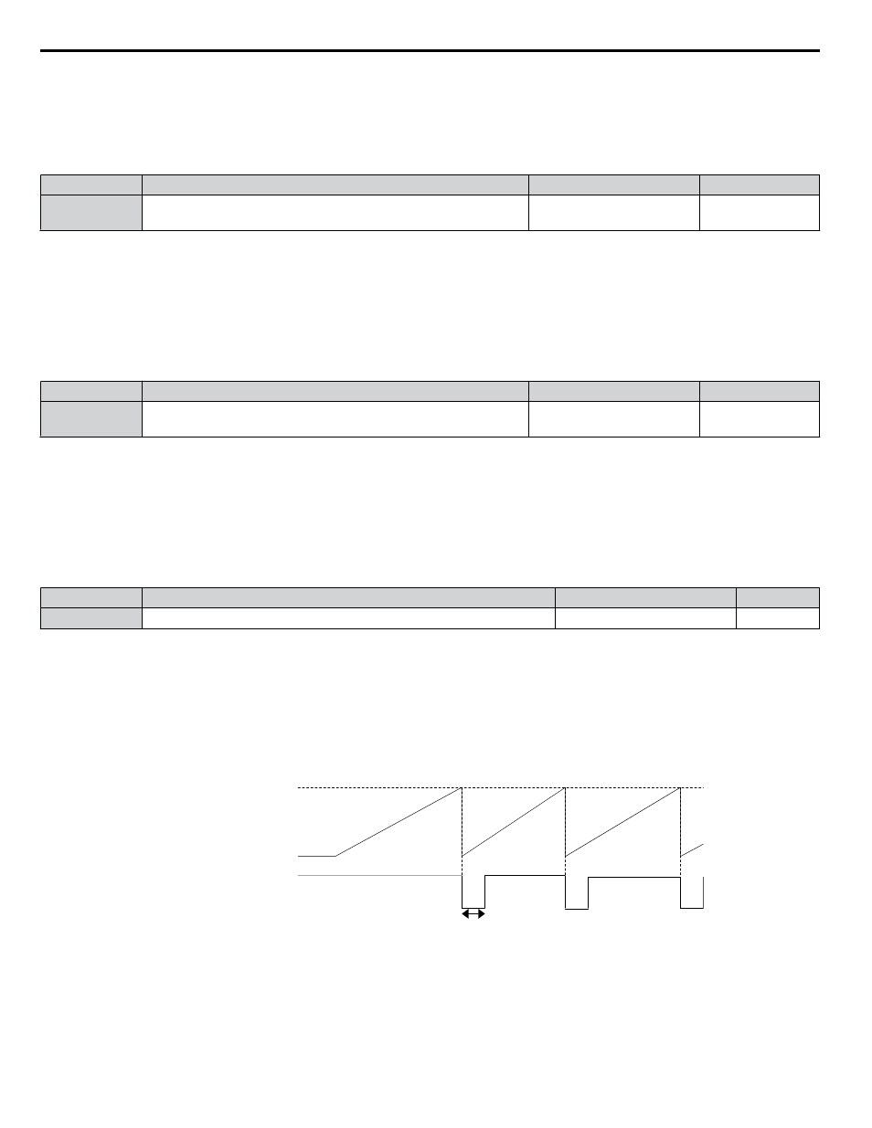
0.2 s
H2-06
(Pulse Output Unit)
H2-01 to H2-03
(Multi-function Output)
Integral Power
OFF
OFF
ON
Figure 4.24 Watt Hour Output Example
n
H3-03, H3-04: Terminal A1 Gain and Bias Settings
Parameter H3-03 sets the level of the selected input value that is equal to 10 Vdc (20 mA) input at terminal A1 (gain).
Parameter H3-04 sets the level of the selected input value that is equal to 0 V (4 mA, 0 mA) input at terminal A1 (bias).
4.7 Basic Drive Setup Adjustments
124
YASKAWA ELECTRIC TOEP C710636 10B Z1000U HVAC MATRIX Drive User Manual